Turning Feature Parameters
Introduction
This topic explains the Feature page of the Lathe Wizard for a Turning feature. This topic will explain the options, provide images, and provide a link to the next topic.
The Feature page
The purpose of Turning is to refine the overall shape of the outer and inner diameters of the part. The Lathe Turning feature offers several operations, each of which has many variables that can be tailored to your needs.
Material Approach
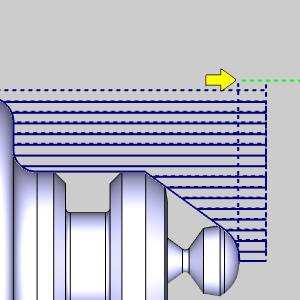
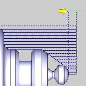
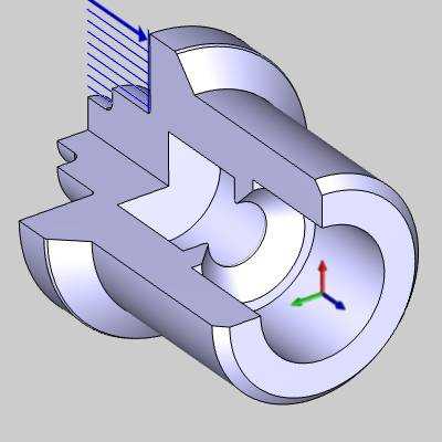
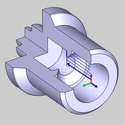
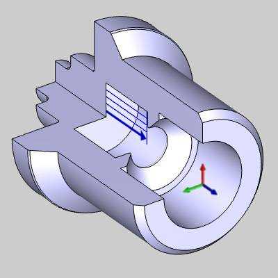
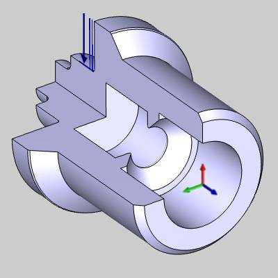
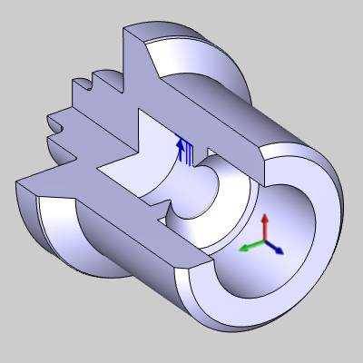
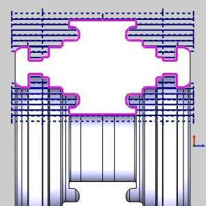
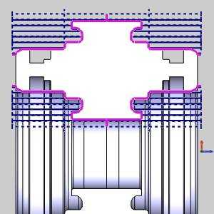
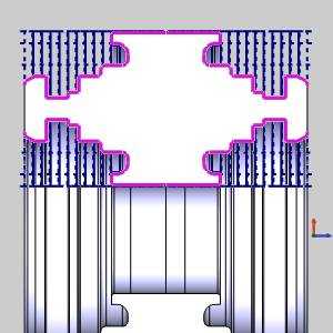
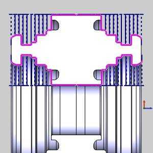
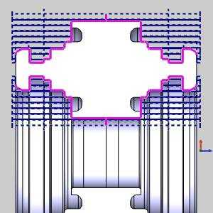
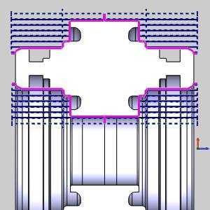
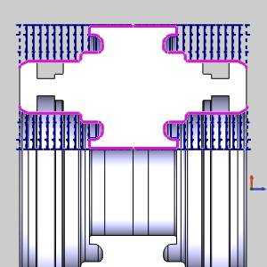
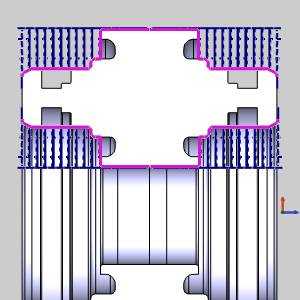
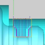
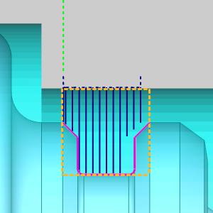
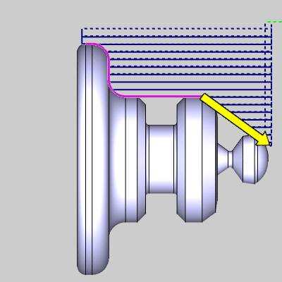
Rapid Plane - is the height at which the tool can rapid safely within a single operation. This value visualized as a dotted line in the toolpath and is an incremental distance above the Top of Feature defined in the Constraints section.
|
Default Rapid |
Higher Rapid Value |
|
|
|
Feature Parameters
Feature Type
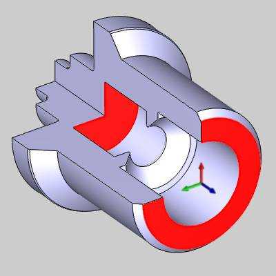
- OD -
Sets the feature to the outer diameter of the part.
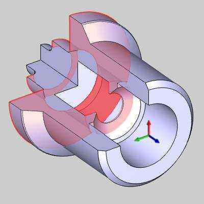
- ID -
Sets the feature to the inner diameter of the part.
- Face -
Sets the feature to faces normal to Z+.
- Back Face - Sets the feature to faces normal to Z-.
Region - Sets the features default settings for the type of toolpath being used. This will set the default rapids, entry and exits as well as default tool selection and direction of cut.
- 1
- See examples.
- 2 - See examples.
|
OD |
OD Region 1 |
OD Region 2 |
|
|
|
|
|
|
|
|
|
ID |
ID Region 1 |
ID Region 2 |
|
|
|
|
|
|
|
|
|
Face |
Face Region 1 |
Face Region 2 |
|
|
|
|
|
|
|
|
|
Back Face |
Back Face Region 1 |
Back Face Region 2 |
|
|
|
|
Note: Region selections are not only for particular sections of the part. Even though, for a given situation, a particular region choice will set the feature up to be better suited for the task, the user may adjust the remaining parameters to match their particular needs.
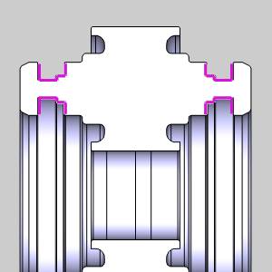
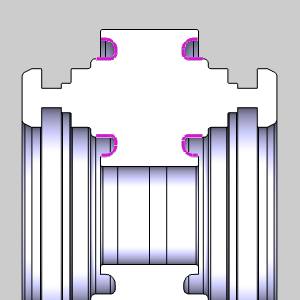
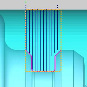
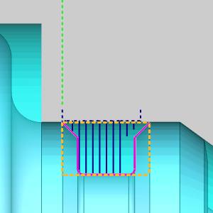
Undercut
The Undercut section provides a way to limit what is being cut in the feature without the need to create additional CAD geometry. See the images and definitions below to get an understanding of what an undercut is defined as.
|
OD, ID |
Front Face, Back Face |
|
|
|
|
Primary Undercut The definition of a Primary Undercut varies depending on the region and feature type. Any geometry on an OD feature that drops in X from the initial start point is considered an area of primary undercut. In the case of an ID feature it is geometry that rises in X from the initial start point. Any geometry on a Front or Back Face feature, that doubles back on itself is considered an area of primary undercut. |
|
|
|
|
|
OD, ID |
Front Face, Back Face |
|
|
|
|
Secondary Undercut The definition of a Secondary Undercut varies depending on the region and feature type. Any geometry on an OD, or ID feature that doubles back on itself is considered an area of secondary undercut. In the case of a Front Face and Back Face OD feature, any geometry that drops in X from the initial start point is considered to be an area of secondary undercut. In the case of a Front or Back Face ID feature, it is geometry that rises in X from the initial start point. |
![]() Remove Primary Undercut - Selecting
this option will force the toolpath to avoid areas defined as Primary
Undercuts.
Remove Primary Undercut - Selecting
this option will force the toolpath to avoid areas defined as Primary
Undercuts.
![]() Remove Secondary Undercut - Selecting
this option will force the toolpath to avoid areas defined as Secondary
Undercuts.
Remove Secondary Undercut - Selecting
this option will force the toolpath to avoid areas defined as Secondary
Undercuts.
|
OD, ID |
|
|
|
|
|
|
|
|
|
|
||
|
Front Face, Back Face |
|
|
|
|
|
|
|
Constraints
The constraints define the area in which the toolpath will be generated.
Top of Feature - Defines the height at which the rapid plane will be incremental from.
-
 From
Stock - Sets the Top of Feature to the highest point of the
stock diameter.
From
Stock - Sets the Top of Feature to the highest point of the
stock diameter.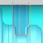
-
 From Geometry - Sets the Top of Feature to the highest point of the selected
feature geometry.
From Geometry - Sets the Top of Feature to the highest point of the selected
feature geometry.
-
Custom
- Set the Top of Feature from the highest point of the selected
feature geometry to the value entered.
-
Pick - allows you to select a point or the snap point of an entity to set the height of the feature.
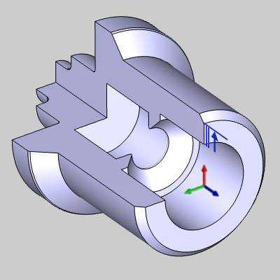
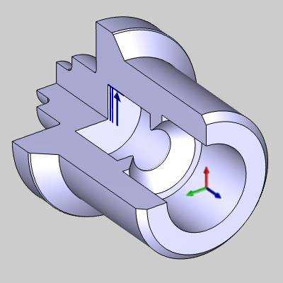
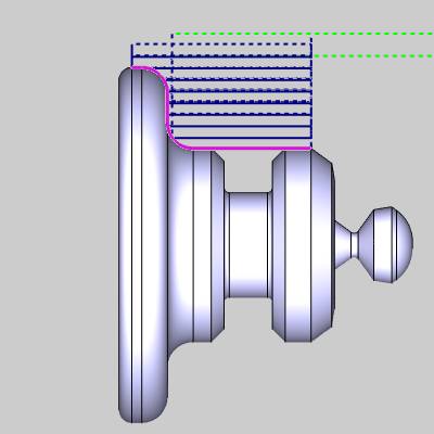
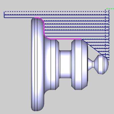
Extension
Extensions allow you to extend the feature geometry without the need to create additional CAD geometry. The extension will be added or subtracted along the chain of entities.
![]() - No extension will be added to the feature geometry.
- No extension will be added to the feature geometry.
![]() - Will allow you to define an extension to the feature geometry.
- Will allow you to define an extension to the feature geometry.
|
|
Extension Off |
|
|
|
|
|
|
|
|
|
|
End Extension |
Start and End Extensions |
Start Extensions |
|
|
|
|
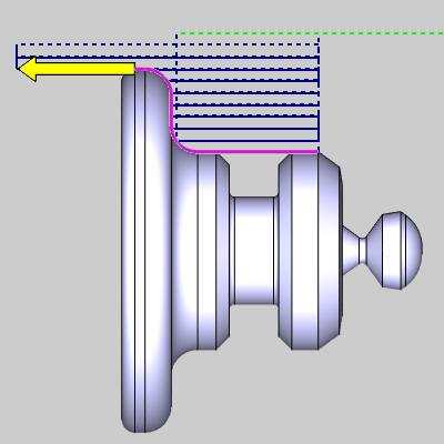
Start - is the first of the selected chain of entities.
- Distance- sets the amount of extension added to the tangent direction
of the chain.
 Angle - While cleared the extension will added to the geometry to the tangent
direction.
Angle - While cleared the extension will added to the geometry to the tangent
direction. Angle- Select
this check box to set the extension at the angle entered.
Angle- Select
this check box to set the extension at the angle entered.- Relative to geometry - Select this check box to set the
angle of the extension relative to the tangency of the first entity. Relative to geometry -
While cleared the angle of the extension will be absolute.
End - is the last of the selected chain of entities.
- Distance - sets the amount of extension added to the tangent direction
of the chain.
- Angle - While cleared the extension will added to the geometry to the tangent
direction. Angle- Select
this check box to set the extension at the angle entered.
- Relative to geometry - Select this check box to set the
angle of the extension relative to the tangency of the last entity. Relative to geometry -
While cleared the angle of the extension will be absolute.
Next Topic
After defining the feature parameters, click Next>> to go to the Machining Strategy page.