 Patterns
Introduction
This topic will explain the Patterns page and all the options found in it. This topic will also provide a link to the next topic.
The Patterns page
The Patterns page gives you control over the pattern of the cut, how that pattern is sorted, and the compensation that will be used to complete the operation.
Pattern
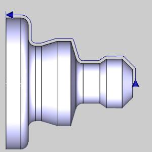
![]() Continuous - sets the finishing
pass to a single pass along the geometry.
Continuous - sets the finishing
pass to a single pass along the geometry.
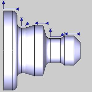
![]() Alternate - breaks the finishing
pass into separate groups defined by either vertical faces, turned diameters,
or a combination of the two.
Alternate - breaks the finishing
pass into separate groups defined by either vertical faces, turned diameters,
or a combination of the two.
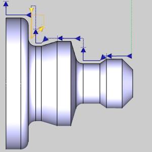
![]() Both - will Face Vertical, and
Turn Diameter with opposing direction of cuts.
Both - will Face Vertical, and
Turn Diameter with opposing direction of cuts. 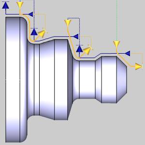
![]() Face Vertical Only - will only
cut vertical walls.
Face Vertical Only - will only
cut vertical walls.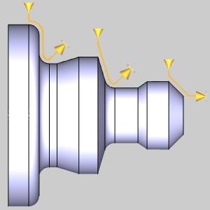
![]() Turn Diameter Only - will only
cut geometry running parallel to the center of rotation.
Turn Diameter Only - will only
cut geometry running parallel to the center of rotation. 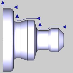
![]() Include angled walls - will allow
for geometries that are not perfectly vertical or horizontal to be cut
as well. This check box is selected by default. See the table below to see how clearing this check box can affect the various selected options.
Include angled walls - will allow
for geometries that are not perfectly vertical or horizontal to be cut
as well. This check box is selected by default. See the table below to see how clearing this check box can affect the various selected options.
|
|
|||||
|
|||||
|
|
|
|
|||
Compensation
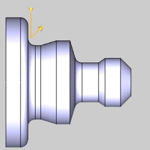
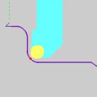
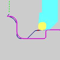
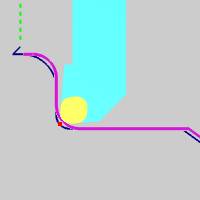
Each tool has a theoretical point placed on it as seen in red in the animation below. In the case of tools with a radius of any size, this point is not actually on the tool, but on the horizontal and vertical intersections of the radius. It is this point that the toolpath plots out. When compensation is used, it is designed to place the actual tool and not just its theoretical point on the geometry. This can be accomplished with System Compensation, Machine Compensation, or a combination of the two.
-
System Compensation
This specifies whether or not the system compensates for the insert geometry and the tool nose radius.
-
Off - the selected geometry is used as the program path; Machine Compensation should be used.
-
On with Collision Detection - the system compensates for the tool nose radius and the insert geometry and avoids any detected collisions.
-
Onwithout Collision Detection - the system compensates for the tool nose radius and the insert geometry without checking for collisions.
| System Compensation: | |||
|
Theoretical Point |
Off |
On with Collision Detection |
On without Collision Detection |
|
|
|
|
|
-
Machine Compensation
Outputs the necessary codes to allow for the user to enter compensation data at the machine. When this is done, the machine will alter the path based on the data entered at the machine. This can even be used in combination with System Compensation in order to compensate for tool wear or other unforeseen variables. -
Off - no compensation commands are output in the posted program.
-
Comp Left / G41 - outputs the left compensation command in the posted program.
-
Comp Right / G42 - outputs the right compensation command in the posted program.
Next Topic
Once the Pattern variables have been set, click Next >> to continue to the Parameters page.