 Leads
Leads
Introduction
This topic explains the options found in the Leads page of the Pocket operation found in the Mill 2 Axis Wizard, and will provide links to related topics.
The Leads page
Entry
-
 Plunge - the tool plunges directly to the start
point of the toolpath.
Plunge - the tool plunges directly to the start
point of the toolpath.

Type
-
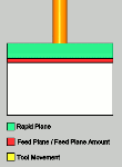
Single Depth - From the Feed Plane, Single
Depth will move at the Plunge Feedrate to the full Depth of Cut.
-
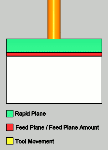
 Peck - From the Feed Plane, Peck will move
at the Plunge Feedrate to the Peck Depth, return to the Feed Plane
with a rapid move, rapid down to a point above the last depth
equal to the amount of the Feed Plane being used, before continuing
to the next Peck Depth amount at the Plunge Feedrate. This method
will be repeated until the full Depth of Cut is reached.
Peck - From the Feed Plane, Peck will move
at the Plunge Feedrate to the Peck Depth, return to the Feed Plane
with a rapid move, rapid down to a point above the last depth
equal to the amount of the Feed Plane being used, before continuing
to the next Peck Depth amount at the Plunge Feedrate. This method
will be repeated until the full Depth of Cut is reached.
- Peck
Depth - sets the increment to use for each peck.
-
Fast Peck - From the Feed Plane, Peck will
move at the Plunge Feedrate to the Peck Depth, Rapid up to an
amount equal the Feed Plane being used, before continuing to the
next Peck Depth amount at the Plunge Feedrate. This method will
be repeated until the full Depth of Cut is reached.
-
Peck Depth - sets the increment to use for each peck.
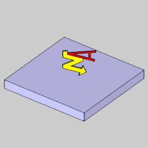
- Ramp
- creates a linear ramp move into the stock. The ramps are automatically
adjusted, based on values entered, so that collision into the model
is avoided. When this option is selected the following boxes become
available.
- Ramp Length/Radius - sets the radius, or length, of the ramp used for entry.
| As Length | As Radius |
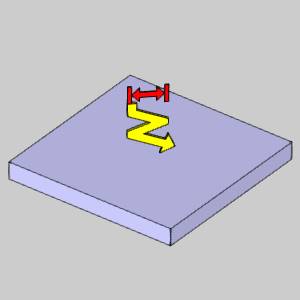
|
|
- Angle of Approach - sets the angle of the toolpath ramp move. When using this option without defining a Maximum Length, the ramp is applied to the entire profile (from the toolpath start point to the top of feature).
Warning: The Ramp approach type does not support collision detection or island avoidance. This should be used with caution.
-
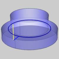
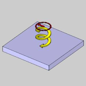
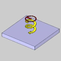
Spiral - generates
a spiral entry into the material. This can be used with the specified
feature Start Point. The movement created always begins at the designated
material top when using a Single Depth, or on the first depth when
using Multiple Depths. When you select the spiral option, the following
options become available (note that the Ramp Radius and Angle of Approach
are the only two parameters available when using the Advanced Pocket
pattern.)
- CW - the spiral approach is generated in a clockwise rotation.
- CCW - the spiral approach is generated in a counter-clockwise rotation.
- Ramp Radius - sets the radius used to create the spiral material entry.
- Angle of Approach - sets the angle of the helical toolpath segments that define the tool approach.

- Spiral Tolerance - sets the interpolation accuracy of the spiral path. The smaller this value is, the smaller the segments are, and the smoother the spiral appears.
- CW - the spiral approach is generated in a clockwise rotation.
Warning: The Ramp approach type does not support collision detection or island avoidance. This should be used with caution.
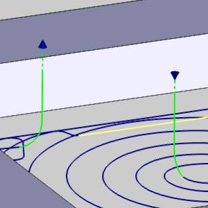
Leads
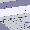
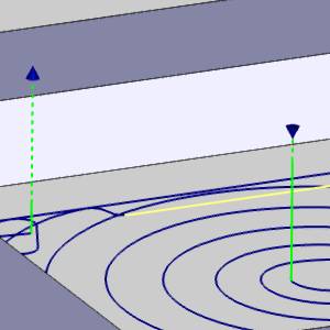
This Leads section is only available when the Adaptive Roughing Pattern
is used. The leads that are available are as follows.
-
Vertical - plunges
directly into the material at the start point of the toolpath and lifts
out at the end.
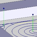
-
Vertical
Arc - attempts to enter and exit the material tangent
to the surface being machined using an vertical arc move.
 MDI (Manual Data
Input)
MDI (Manual Data
Input)
View the MDI topic.
Related Topics
Modifying the Plunge Location
You can modify the plunge location for pocketing operations as explained in Pocket Plunge Locations.
Clicking Next> > takes
you to the next page of the Mill 2 Axis Wizard. To move to the corresponding
topic, click the appropriate link below.
The Profile Rough Machine
Sequence page
The Profile Finish Machine Sequence page
The Pocket Machine Sequence page
The Corner Rounding Machine Sequence page