Geometry Selection
Introduction
The first step of the Mill 2 Axis Wizard is to assign geometry for the feature. All operations in the feature are performed on the selected geometry. This can be a single entity or multiple entities . The Geometry Selection dialog box appears similar to the following.
 Geometry Selection
Geometry Selection
The Mill 2 Axis Feature use wireframe geometry such as lines, arcs, splines, points, surfaces/solids, or the edges of solids/surfaces. When selecting surface geometry, all of the edges (holes, bosses, islands) are extracted from the solid and they are automatically projected to a flat plane (Top of Feature).
- Select Geometry - Clicking the Select Geometry
button launches the
Re/Select Geometry
![]() (OK) -
confirms the geometry and closes the Feature Geometry Picking manager.
(OK) -
confirms the geometry and closes the Feature Geometry Picking manager.
![]() (Cancel) -
cancels geometry selection and closes the Feature Geometry Picking manager.
(Cancel) -
cancels geometry selection and closes the Feature Geometry Picking manager.
-
 Select whole bodies - allows you to select entire bodies at once.
  Select whole bodies - allows you to select the individual edges, and faces of a body.
Selected
Parameters
-
Auto group - Select the check box to allow the software to automatically group similar machining operations together in order to minimize the amount of features based on the selected geometry. Auto group - Clear the check box to force the software to create separate machining features of the same type for each selected shape.
- Rapid Plane - sets the rapid height for the feature as an incremental value from the Top of Feature. This defines the default value used in the CAM Wizard.
- Tolerance - is a selection tolerance that is used in the feature detection based on the type of selection made. For most scenarios, you should not have to change this value.
-
Gouge check - allows the system to gouge check the feature. The Horizontal Extension check box becomes available. Gouge check - does not gouge check the feature, and the Horizontal Extension option becomes unavailable.
-
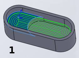
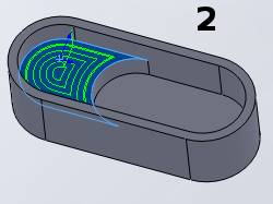
Horizontal extension - allows the software to make adjustments to the boundaries of the selected geometry to provide a more optimal toolpath. For example, when creating pockets of multiple depths. This can be used to extend a selected surface to the boundaries of the part and have the feature cut the entire area to the same depth. This is shown in the following example. Horizontal extension - does not gouge check the feature, and the Horizontal Extension option becomes unavailable.
|
|
|
|
|
Next Topic
After selecting geometry and making any necessary changes, click Next>> to go to The Mill 2 Axis Wizard Feature Settings.