The Mill Wizard Tabs Settings
Introduction
This topic explains the Tabs page that displays in the Mill 2 Axis Wizard. This page contains all of the parameters for defining tabs for profile operations. Tabs allow you to have the tool retract at specified locations along a profile cut for the purpose of leaving material that holds the part in place.
Note: Tabs can only be applied to Profile Rough and Profile Finish operations.
The Tabs List
The tabs list displays all chains that are selected for the feature, and displays the Chain ID, Type, Width, Angle, and Height parameters for all tabs that are applied to each chain. When defining the tabs, you select a chain in the list and then modify its parameters under Apply Tab and Tab Geometry.
Turning On Tabs for One or All Chains
You can select the check box at the top of the tabs list to turn on tabbing for all chains in the list. Otherwise, you can select the check box next to a specific chain in the list to turn on tabbing for that chain only. Note that you can also select a chain in the tabs list, and then select the Apply Tabs check box that displays below the list.
Turning On and Off Tabs for Operations
The Patterns page of profile operations contains the Apply Tabs check box for turning tabbing on or off for the operation. When you turn on tabbing in the Tabs page of the Mill 2 Axis Wizard, the software automatically turns on the Apply Tabs option for all profile operations in the feature. You can clear the Apply Tabs check box on the Patterns page to turn off tabbing for that operation. Note that this option does not display on the Patterns page until tabbing is turned on for at least one chain.
Defining Tabs
Both the Apply Tabs and Tab Geometry groups of the Tabs page contain the parameters for defining tabs as explained next.
Apply Tab
After selecting a chain in the tabs list, you can then define the number and location of tabs for the chain with the following parameters. The Apply Tabs check box must be selected to turn on tabbing and enable the parameters used to define the number and location of tabs for the currently selected chain.
![]() - No tabs are applied.
- No tabs are applied.![]() - Tabs are enabled with the following options.
- Tabs are enabled with the following options.
- Use
Manual Tabs
 Select the check box to enable the
Edit Tabs button.
Select the check box to enable the
Edit Tabs button. Clear the check box to define the tabs using either the Number of Tabs
or Length Between Tabs options.
Clear the check box to define the tabs using either the Number of Tabs
or Length Between Tabs options.
- Edit Tabs
After selecting the Use Manual Tabs check box, click Edit Tabs to select the tab locations directly from the geometry in the graphics area. The tab locations display as a point along the chain. You can click the current tab points to remove them, and click the new locations to which you want to apply tabs. You can select as many tab points as needed, but tabs can only be placed along the chain using the available snap point locations. After selecting manual tab locations, click (OK) to return to the wizard.
- Edit Tabs
Important: When selecting manual tab locations, you are only selecting tabs for the chain that is currently selected in the tabs list, not all chains.
- Automatic Tabs
When the Use Manual Tabs check box is cleared, you can automatically define the tab locations using one of two options: Number of Tab or Length Between Tabs. These options create equally spaced tabs along the feature using one of two methods.- Number
of Tabs - is used to define the tab locations using a number
of specified tabs. The software automatically creates the tab locations,
using an equal distance between tabs (from the chain start point),
based on the value in the Number of Tabs box.
- Length
Between Tabs - is used to define the tab locations by specifying
a Minimum Length Between tabs. Note that this value should be less
than the total chain length and greater than the tab width plus the
tool diameter. This distance is evenly applied from the chain start
point and the actual distance between tabs may be greater.
- Apply to Active Chains
When defining tabs automatically, this button applies the current settings (Number of Tabs or Length Between Tabs) to all chains that are currently selected (active) in the chains list. (Active refers to chains in the list that have the check box selected.)
- Number
of Tabs - is used to define the tab locations using a number
of specified tabs. The software automatically creates the tab locations,
using an equal distance between tabs (from the chain start point),
based on the value in the Number of Tabs box.
Tab Geometry
The following parameters allow you to change the shape of the tab. These settings determine the length of the tab, the angle at which the tool moves to cut the tab, and the height of the tab from the cutting depth.
Apply Leads
![]() When this check box is cleared, no
leads will be applied to the tabs.
When this check box is cleared, no
leads will be applied to the tabs.![]() When selected, you will be able to
create a perpendicular lead consisting of a radius and a perpendicular
line.
When selected, you will be able to
create a perpendicular lead consisting of a radius and a perpendicular
line.
- No lead out
When this check box is cleared, lead
outs will be applied to the tabs.When selected, no lead outs will be
applied to the tabs.
- Length - This is the length of the perpendicular
line.
- Radius
- allows you to create a radial transition between the toolpath
and the perpendicular length of the lead.
Important: When creating tabs, it should be noted that the tab width is calculated before the radii are added. If you need the tab to be an exact size, be sure to factor in the addition of the two radii. The Radius value can be set to zero if need be.
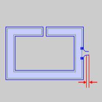
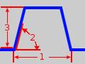
- Width (1) - sets
the tab width. This is the width at the bottom of the tab regardless
of the tab angle. Note that the width of the toolpath is the tab width
plus the tool diameter.
- Angle (2) - setsthe tab angle. The default is 90
which causes a vertical retract and a vertical plunge back into the
part. An angle less than 90 degrees causes the tool to ramp over the
tab. The angle must be between 0 and 90 degrees.
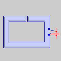
- Height (3) - setsthe tab height. For a full tab,
the height should be equal to or greater than the cut depth. Partial
tabs can be achieved by entering a value less than the full cut depth.
- Apply
to Active Chains
When defining the tab geometry, this button applies the current settings (Width, Angle, and Height) to all chains that are currently selected (active) in the chains list. (Active refers to chains in the list that have the check box selected.)
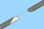
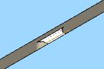
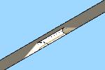
Shown below are the different tab types that
can be achieved. From left to right: Full tab, Full tab with ramp,
Partial tab, Partial tab with ramp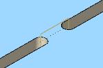
Warning: After creating a toolpath with tabs defined, if you modify the geometry assigned to the feature, you need to update the settings in the wizard for those chains. This applies to adding geometry or modifying the current geometry. The software automatically matches the tabbing parameters for geometry that has not changed, but it cannot apply tabs from previous geometry to newly created or modified geometry.
Next Topic
After defining the tabbing, click Next>> to go to the Posting Settings for the feature.