 Patterns
Introduction
This topic explains the Patterns page of the Advanced Planar operation found in the Mill 3 Axis Wizard.
 Patterns
Cut Pattern
 Zig
- creates the operation so each pass of the tool follows the same
general direction (one way machining).
Zig
- creates the operation so each pass of the tool follows the same
general direction (one way machining).
 Zig Zag
- creates the operation so each pass of the tool alternates direction
from the previous pass.
Zig Zag
- creates the operation so each pass of the tool alternates direction
from the previous pass.
- Up - separates the model
into high and low regions and performs all cuts from the bottom of
the model upward.
-
Down - separates the model into high and
low regions and performs all cuts from the top of the model downward.
Lace Angle - determines the direction of the toolpath passes in reference to the machining origin. The default value of 90 degrees generates passes that are parallel to the Y-axis, and a value of 0 degrees generates passes that are parallel to the X-axis of the machining origin.
- Overlap Distance - determines how much the opposing
toolpath slices at the top of the model overlap when using the
Up or Down Cut Pattern. This can help to reduce scallops at the
top of the model.
- Minimum Height Change - determines the minimum allowed change in height that will separate the model into up or down cuts when using the Up or Down Cut Pattern. This can be used to keep the toolpath from splitting across shallow portions of the model.
Start Corner
To set the starting location of the operation on the model select either Upper Left, Upper Right, Lower Left, or Lower Right.
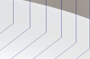
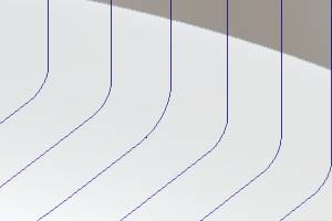
Round Corners
The Round Corners option allows you to specify a maximum deviation value
which allows a radius within that range to be substituted in place of
sharp corners. To turn this option on, click the Round
Corners check box. You can then type the maximum deviation possible
for the round corners in the Maximum
Deviation box. To turn this option off, clear the Round Corners
check box.
|
|
|
|
|