 Parameters
Introduction
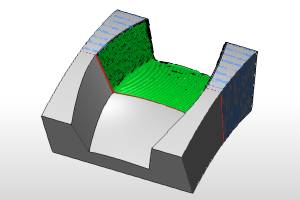
This topic explains the Parameters page of the Flatlands operation found in the 3 Axis Wizard.
 Parameters
Finish
-
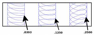
Stepover - the distance between each pass.
-
(Climb) Stepover - the distance between each pass. When Zig Zag is selected for the pattern, this will be read as Climb Stepover to allow a variance between the climb and conventional passes.
-
 Conventional Stepover
- When Zig Zag is selected for the pattern you will be able to
select this check box to list a different value for the Convention
pass than has been listed for the Climb Stepover.
Conventional Stepover
- When Zig Zag is selected for the pattern you will be able to
select this check box to list a different value for the Convention
pass than has been listed for the Climb Stepover.  Conventional
Stepover - Leaving this check box cleared will leave both
climb and conventional setup to the value entered Climb Stepover.
Conventional
Stepover - Leaving this check box cleared will leave both
climb and conventional setup to the value entered Climb Stepover.
-
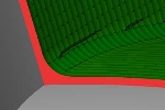
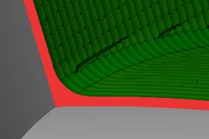
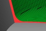
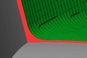
Min. Width of Flatlands - any flat areas with a width smaller than the given value are ignored.
-
Max. Width of Flatlands - sets the maximum width of flat areas that are included in the flatlands machining.
![]() Select this check
box to set a maximum width of flat areas that are included.
Select this check
box to set a maximum width of flat areas that are included.
![]() Clear the check box to only set a minimum width of flat areas that are
included.
Clear the check box to only set a minimum width of flat areas that are
included.
-
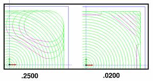
Machining Tolerance - the amount of variation allowed for creating the toolpath for the feature. The accuracy of the toolpath does not exceed this range.
Note: The Minimal Curvature Radius is only available when using the Adaptive Roughing pattern.
-
Minimal Curvature Radius - determines the smallest radius used in the toolpath motion. This value must be greater than zero, but be aware that if you set this value too high, no toolpath is created. This parameter is useful, for example, to determine how far into a corner the toolpath can reach.
-
 Cut Holes - extends the toolpath
into any holes that may be present in the surface.
Cut Holes - extends the toolpath
into any holes that may be present in the surface. -
 Ignore Holes - does not place the
toolpath into any holes and treats the surface as if it is continuous
and unbroken.
Ignore Holes - does not place the
toolpath into any holes and treats the surface as if it is continuous
and unbroken.
Depth Options
- Top of Job
- sets the highest Z location for toolpath
as the top of stock. -
allow you to specify the highest Z location for toolpath in this operation.
Select the check box and type a value to define a plane for the top
of job.- Pick - hides the Wizard to allow
you to set the Top of Job by selecting geometry whose height, in relation to the machine setup, is at the desired value.
- Pick - hides the Wizard to allow
you to set the Top of Job by selecting geometry whose height, in relation to the machine setup, is at the desired value.
- Bottom of Job
- sets the lowest Z location for
toolpath as the bottom of stock. -
allows you to specify the lowest Z location for toolpath in this operation.
Select the check box and type a value to define a plane for the bottom
of job.- Pick - hides the Wizard to allow you to set the Top of Job by selecting geometry whose height, in relation to the machine setup, is at the desired value.
Note: The Bottom of Job and Top of Job values are in reference to the machining origin (Machine Setup coordinate) of the part.
Allowance
The Allowance settings are used to define the rest material, or the amount of material remaining after this operation to be removed by the next operation, in one of two ways. These options offset the model geometry to calculate the toolpath. You can use positive or negative values to leave extra material or cut deeper than the model geometry, respectively.
Offset Type
The Offset Type determines if the allowance is applied to the entire model or separately for the bottom and sides of the part. Select one of the following options and then type the allowance value in the available allowance boxes.
- Global
- applies a single allowance value to the entire model using the Allowance
XYZ value.
- Allowance
XYZ - is the amount of material left on the entire model
(XYZ).

- Side
and Bottom - allows you to specify separate allowances for
the side (XY) and bottom (Z) of the part.
- Side
Allowance - is the amount of material left on the sides
of the part (XY).
- Bottom
Allowance - is the amount of material left on the bottom
of the part (Z).
- Advanced - opens the Allowances dialog to allow you to select surfaces to assign as either Part, or Fixture, geometry items. Each of those items can then have specific allowances set. - With this check box cleared, only the Offset Type and Allowance above will be used for the Feature Geometry.
- With this check box selected, the geometry and allowances set in the (Advanced) Allowances dialog will be active.