 Options
Introduction
This topic explains the Options page found in the Project Curves operation of the Mill 3 Axis Wizard.
 Options
Limits
Boundary Options
Boundaries are used to contain the toolpath of the operation to stay within the specified area. The Boundary Options determine where the tool cuts when it reaches the boundary in one of three ways.
-
 Center of
Tool - forces the center of the tool to cut directly on the
specified boundary.
-
 Tool Inside
- forces the entire tool to stay inside of the boundary. (This offsets
the toolpath to the inside of the boundary by the tool radius.)
- Offset - is used to add an additional offset to the location of the tool at the boundary when using Tool Inside or Tool Outside. When using Tool Inside, the tool stays inside of the boundary by the specified distance. When using Tool Outside, the tool goes outside of the boundary by the specified distance. Note that positive or negative values are supported.
-
 Tool Outside
- forces the entire tool to go outside of the boundary. (This offsets
the toolpath to the outside of the boundary by the tool radius.)
- Offset - is used to add an additional offset to the location of the tool at the boundary when using Tool Inside or Tool Outside. When using Tool Inside, the tool stays inside of the boundary by the specified distance. When using Tool Outside, the tool goes outside of the boundary by the specified distance. Note that positive or negative values are supported.
Other
Rest Finishing
![]() - No rest finishing will be used.
- No rest finishing will be used.
![]() - When this check box is selected,
BobCAD-CAM calculates the toolpath to remove all the non-machined
areas that remain. On intricate parts it is possible to run multiple
rest rough toolpaths to remove as much material as possible before
running semi finishing or finishing toolpaths. With Rest Finishing
toolpaths you normally use a smaller step down, as the cutter size
reduces, than have been used with the previous cutter.
- When this check box is selected,
BobCAD-CAM calculates the toolpath to remove all the non-machined
areas that remain. On intricate parts it is possible to run multiple
rest rough toolpaths to remove as much material as possible before
running semi finishing or finishing toolpaths. With Rest Finishing
toolpaths you normally use a smaller step down, as the cutter size
reduces, than have been used with the previous cutter.
Note: The Use Previous Operation check box doesn't display unless you have another operation previous to the current operation in the feature.
-
 Tool
from Previous Operation - When this
radio button is selected, BobCAD-CAM will use the tool information from
the previous operation to calculate the rest finishing pass.
 - Previous Tool
Diameter - will be disabled
and use the tool information from the previous operation.
- Previous
Corner Radius - will be disabled
and use the tool information from the previous operation.
- Expand Rest Area - allows you to manually extend the area to be rest roughed, in order to ensure overlap.
- Previous Tool
Diameter - will be disabled
and use the tool information from the previous operation.
-
 User Defined Tool - will allow you to enter
tool information manually.
User Defined Tool - will allow you to enter
tool information manually.- Previous Tool
Diameter - Enter the previous tool diameter
here and BobCAD-CAM will calculate what stock would be remaining
in order to compute tool path for the current tool. Be sure
to enter a diameter larger than the tool used for this operation.
- Previous
Corner Radius - Enter the previous tool radius
here and BobCAD-CAM will calculate what stock would be remaining
in order to compute tool path for the current tool.
- Expand Rest Area - allows you to manually extend the area to be rest roughed, in order to ensure overlap.
- Previous Tool
Diameter - Enter the previous tool diameter
here and BobCAD-CAM will calculate what stock would be remaining
in order to compute tool path for the current tool. Be sure
to enter a diameter larger than the tool used for this operation.
-
 Stock
STL - will allow you to use the Rest
Stock STL button to select an STL model for BobCAD-CAM to compare to the
selected geometry. Once the STL is compared to the geometry the toolpath
will be created where the STL model extends beyond the selected geometry.
Stock
STL - will allow you to use the Rest
Stock STL button to select an STL model for BobCAD-CAM to compare to the
selected geometry. Once the STL is compared to the geometry the toolpath
will be created where the STL model extends beyond the selected geometry.- Detect thicker
than - allows you to enter
a value to ignore. For instance, if an allowance has been left
for finishing by another operation, entering that amount will
have this operation leave that allowance.
- Rest Stock STL - launches the Load Stock File dialog to allow you to select an .stl file which will be used to dictate the remaining stock to be machined.
Tip: The simulation will allow you to save out the remaining stock as an STL model. It is recommended that you simulate the previous operations and then save out the remaining stock as an STL. For more information about this process, see the Save Stock Material section in The File Tab (Simulation).
- Expand Rest Area - allows you to manually extend the area to be rest roughed, in order to ensure overlap.
- Detect thicker
than - allows you to enter
a value to ignore. For instance, if an allowance has been left
for finishing by another operation, entering that amount will
have this operation leave that allowance.
Point
- Calculate From
- Tool Tip - calculates
the toolpath from the tool tip.
- Tool Center - calculates the toolpath from the center of the bottom of the tool, in the case of a straight cornered end mill, or from the center of the radius on the tool, in the case of bullnose or ball-end mills.
- Tool Tip - calculates
the toolpath from the tool tip.
Angle Range
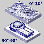
The Angle Range parameters allow you to define an angle interval for which the toolpath is created. You can machine inside of the range or outside of the range. This allows you to define steep and shallow areas of the part model so you can optimize the operation.
![]() - The toolpath will not be limited by the Angle Range.
- The toolpath will not be limited by the Angle Range.
![]() - The toolpath will be limited based on the Angle Range values.
- The toolpath will be limited based on the Angle Range values.
Slope Angles
- Angle
Start - determines the starting angle for the angle range.
This value must be between 0-90 degrees and it must be less than the
Angle End.
- Angle End - determines the ending angle for the angle range. This value must be between 0-90 degrees and it must be greater than the Angle Start.
Machining Area
-
 Machine
Between Slope Angles - forces the operation to only create
toolpath inside of the Slope Angles.
 -
 Machine Outside Slope Angles - forces the operation
to only create toolpath outside of the Slope Angles.


