 Patterns
Introduction
This topic explains the Patterns page of the Project Curves operation found in the Mill 3 Axis Wizard.
 Patterns
Cut Pattern
-
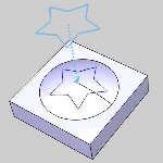
Pick Projection Curves - enables selection mode for you to select the projection curve geometry. Click OK to confirm your selections and return to the wizard. The projection curves can be wireframe geometry which is projected along the Z-axis onto the model or you can select edges directly from the part model.
-
Type - determines how the toolpath is created from the projection curves using one of the two following options.
-
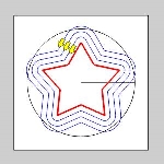
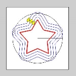
User Defined - creates the toolpath directly from the selected projection curves. A single pass is applied to the selected projection curves.
-
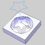
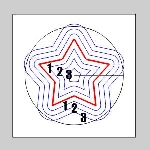
Offset - creates the toolpath using the selected projection curves and then creates offsets of the curves. The area of the model and the number of cuts that are applied from the projection curves are then determined by the Step Direction and Number of Cuts parameters.
Note: The Step Direction and Number of Cuts parameters are only available when the Type is set to Offset.
-
Step Direction - determines the direction in which the toolpath is applied from the projection curves.
-
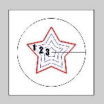
Left - applies the toolpath to the left of the chain direction of the projection curves for open shapes. For closed shapes, this creates the toolpath inside of the shape regardless of the chain direction.
-
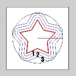
Right - applies the toolpath to the right side of the chain direction of the projection curves for open shapes. For closed shapes, this creates the toolpath outside of the shape regardless of the chain direction.
-
Both - applies the toolpath to both sides of the projection curves.
The Step Direction parameter is then used in conjunction with the Number of Cuts parameters explained next.
-
Number of Cuts Left - defines the number of passes that are created to the left side of the selected projection curves when using Step Direction Left or Both.
-
Number of Cuts Right - defines the number of passes that are created to the right side of the selected projection curves when using Step Direction Right or Both.
Important: When the Number of Cuts parameters are set to zero, the operation applies as many offsets of the curves as possible based on the feature and selected parameters. When greater than zero, the software creates a pass on the projection curves plus the value specified for the Number of Cuts parameters. For example, when setting the Number of Cuts to two, three passes are created.
Method
 Zig
- creates the operation so each pass of the tool follows the same
general direction (one way machining).
 Zig Zag
- creates the operation so each pass of the tool alternates direction
from the previous pass.
- User Defined - means that you define the cutting method by setting the chain direction for all projection curves, which is set using the Drive Curves item in the CAM Tree. This option is only available when the Type is also set to User Defined.
Cut Direction
-
 Climb
Mill - the tool travels in a counter
clockwise direction along the inside shapes of the model and travels
in a clockwise direction along the outside edges of the model.
 -
 Conventional Mill - the tool travels in a clockwise direction
along the inside shapes of the model and travels in a counter clockwise
direction along the outside edges of the model.
Sorting
The following options are only available when the Type is set to Offset.
-
 Standard - machining starts
from the outer most loop on the part and progresses inwards.
 -
 Center Away - machining
starts from the inside and progresses outwards within each region.
 -
 Outside to Center - machining
starts from the outside and progresses inwards within each region.
