Important: The Group Retracts handle the safe rapid distance between Hole Groups, not within them. The Rapid Plane value determines the safe rapid distance within Hole Groups.
This information applies to standard drilling, multiaxis drilling, and cross drilling (Mill Turn). You can select a plane, cylinder, or sphere to use as the rapid area between groups as explained in this topic. Each option alters the remaining options in the dialog, so in this section you will notice a different group for each Type option.
Group Retracts Dialog
Type
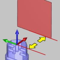
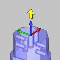
Plane
Plane is the default retract setting
defined using the following parameters.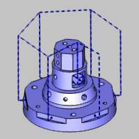
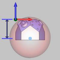
- Height
This parameter defines the plane's distance from the machine setup (machining origin) location, along the selected Axis.

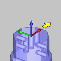
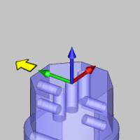
Axis
This parameter determines the direction in which the tool retracts to reach the plane with one of the following options.
- X
Axis - the tool retracts in the X-axis direction.
- Y Axis - the tool retracts
in the Y-axis direction.
- Z Axis - the tool retracts
in the Z-axis direction.
- User Defined - allows you to define a custom retract direction. Once this option is selected, the Direction parameter becomes available for you to define the retract direction.
Direction
The Direction group displays the
direction vector of the selected plane (Axis). When selecting
X Axis, Y Axis, or Z Axis, this in an informational display only.
(For example, when set to Y Axis, the vector displays as X0 Y1
Z0.) When selecting User Defined, you can type values to determine
the custom direction vector, or you can click  to set the direction by selecting a line in the graphics area.
Note: The Direction vector is always in reference to the feature's coordinate system. Generally, this is the Machine Setup (or machining origin), but if the feature is under an index system, then it is in reference to the index coordinate system.
Group Retracts Dialog
Type
Cylinder
Cylinder creates a cylindrical retract
area around the part, which is especially useful for 4-axis, mill
turn, or multiaxis machining. The tool retracts radially to the
outer circumference of the cylinder before moving to the next
operation. The cylinder is defined using the following parameters.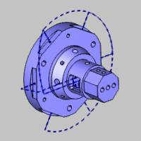
- Radius
This parameter defines the radius, or half the diameter, of the cylindrical retract area.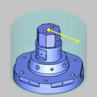
Retract Direction
This option determines how the tool moves to reach the retract area in one of two ways.
- Shortest Distance -
forces the tool to retract to the clearance area directly
or using the shortest distance possible (from the last
tool position of the operation to the clearance area).

- Tool Orientation - forces
the tool to retract to the clearance area following to
tool orientation of the last tool position for the operation.
Axis
This parameter determines the orientation of the cylindrical retract area in relation to the machine setup (machining origin).
- X
Axis - the cylindrical retract area is parallel
to the X-axis.

- Y Axis - the cylindrical retract area is parallel
to the Y-axis direction.

- Z Axis - the cylindrical retract area is parallel
to the Z-axis direction.

- User Defined - allows you to define a custom orientation for the cylindrical retract area. Once this option is selected, the Direction parameter becomes available for you to define the direction.
Direction
The Direction group displays the
direction vector of the selected plane (Axis). When selecting
X Axis, Y Axis, or Z Axis, this in an informational display only.
(For example, when set to Y Axis, the vector displays as X0 Y1
Z0.) When selecting User Defined, you can type values to determine
the custom direction vector, or you can click
to set the direction by selecting a line in the graphics area.
Note: The Direction vector is always in reference to the feature's coordinate system. Generally, this is the Machine Setup (or machining origin), but if the feature is under an index system, then it is in reference to the index coordinate system.
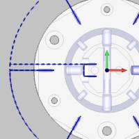
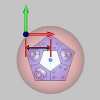
Base Point
This parameter determines an offset of the clearance area in reference to the machine setup (machining origin) along each of the three coordinate axes. This setting is helpful for when the machining origin does not align with the rotational axis of the part.
- X - determines the distance
from the machining origin to the center of the retract
area along the X-axis of the machining origin.
- Y - determines the distance
from the machining origin to the center of the retract
area along the Y-axis of the machining origin.
- Z - determines the distance
from the machining origin to the center of the retract
area along the Z-axis of the machining origin.
-
- click this button to set the Base Point
by selecting geometry in the graphics area.
Tip: When adjusting the Base Point parameter for a cylindrical retract area, generally, you should only need to adjust two of the three values. For example, with a Z Axis cylinder, only the X and Y values need updated to move the base point, and with an X Axis cylinder, you should only adjust the Y and Z values. Adjusting the base point parameter that is the same as the selected Axis does not change the retract area for the cylinder type (the height of the cylinder is essentially infinite).

Angle Step for Rapid Moves
This parameter is the threshold for the maximum segment length (defined by an angle) around the cylinder for rapid moves. Imagine the radius of a cylinder drawn at zero degrees. With an angle step of three degrees, another radius is drawn every three degrees from the starting radius. Each radial line intersects the outside diameter with the distance between each intersecting point defining the segment length.
|
Angle Step = 5 Degrees |
Angle Step = 45 Degrees |

|

|
Group Retracts Dialog
Type
Sphere
Sphere creates a sphere shaped retract
area defined using the following parameters. This retract type
is helpful for multiaxis machining, for example, with parts such
as impellers.
- Radius
This parameter defines the radius, or half the diameter, of the spherical retract area.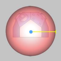
Retract Direction
This option determines how the tool moves to reach the retract area in one of two ways.
- Shortest Distance -
forces the tool to retract to the clearance area directly
or using the shortest distance possible (from the last
tool position of the operation to the clearance area).
- Tool Orientation - forces
the tool to retract to the clearance area following to
tool orientation of the last tool position for the operation.
Base Point
This parameter determines an offset of the clearance area in reference to the machine setup (machining origin) along each of the three coordinate axes. This setting is helpful for when the machining origin does not align with the rotation axis of the part.
- X - determines the distance
from the machining origin to the center of the retract
area along the X-axis of the machining origin.
- Y - determines the distance
from the machining origin to the center of the retract
area along the Y-axis of the machining origin.

- Z - determines the distance
from the machining origin to the center of the retract
area along the Z-axis of the machining origin.
-
- click this button to set the Base Point
by selecting geometry in the graphics area.
Tip: When adjusting the Base Point parameter for a cylindrical retract area, generally, you should only need to adjust two of the three values. For example, with a Z Axis cylinder, only the X and Y values need updated to move the base point, and with an X Axis cylinder, you should only adjust the Y and Z values. Adjusting the base point parameter that is the same as the selected Axis does not change the retract area for the cylinder type (the height of the cylinder is essentially infinite).
Angle Step for Rapid Moves
This parameter is the threshold for the maximum segment length (defined by an angle) around the cylinder for rapid moves. Imagine the radius of a cylinder drawn at zero degrees. With an angle step of three degrees, another radius is drawn every three degrees from the starting radius. Each radial line intersects the outside diameter with the distance between each intersecting point defining the segment length.
|
Angle Step = 5 Degrees |
Angle Step = 45 Degrees |
|
|
|