The Mill Hole Wizard Counterbore Tap Feature Page
Introduction
The second step of the Mill Hole Wizard is to define the Feature Parameters. These parameters define rapid movement and depth settings that are applied to all operations in the feature. Also, many drilling operation depths can be overridden in the Parameters settings. All of the parameters found in the Feature dialog box are explained in this topic. The Feature Pages give you control of Material Approach, Feature Parameters, Parameters, Thread Direction and Hole Groups.
Material Approach
- Group Retracts - opens the Groups Retract dialog box for you define the safe rapid distance between Hole Groups. This value is incremental from the Machine Setup (machining origin) location.
Important: The Group Retracts handle the safe rapid distance between Hole Groups, not within them. The Rapid Plane value determines the safe rapid distance within Hole Groups.
![]() Click here to expand on the subject
of Group Retracts.
Click here to expand on the subject
of Group Retracts.
Important: The Group Retracts handle the safe rapid distance between Hole Groups, not within them. The Rapid Plane value determines the safe rapid distance within Hole Groups.
This information applies to standard drilling, multiaxis drilling, and cross drilling (Mill Turn). You can select a plane, cylinder, or sphere to use as the rapid area between groups as explained in this topic. Each option alters the remaining options in the dialog, so in this section you will notice a different group for each Type option.
Group Retracts Dialog
Type
Plane
Plane is the default retract setting
defined using the following parameters.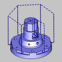
- Height
This parameter defines the plane's distance from the machine setup (machining origin) location, along the selected Axis.

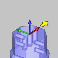
Axis
This parameter determines the direction in which the tool retracts to reach the plane with one of the following options.
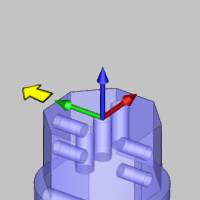
- X
Axis - the tool retracts in the X-axis direction.
- Y Axis - the tool retracts
in the Y-axis direction.
- Z Axis - the tool retracts
in the Z-axis direction.
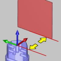
- User Defined - allows you to define a custom retract direction. Once this option is selected, the Direction parameter becomes available for you to define the retract direction.
Direction
The Direction group displays the
direction vector of the selected plane (Axis). When selecting
X Axis, Y Axis, or Z Axis, this in an informational display only.
(For example, when set to Y Axis, the vector displays as X0 Y1
Z0.) When selecting User Defined, you can type values to determine
the custom direction vector, or you can click  to set the direction by selecting a line in the graphics area.
Note: The Direction vector is always in reference to the feature's coordinate system. Generally, this is the Machine Setup (or machining origin), but if the feature is under an index system, then it is in reference to the index coordinate system.
Group Retracts Dialog
Type
Cylinder
Cylinder creates a cylindrical retract
area around the part, which is especially useful for 4-axis, mill
turn, or multiaxis machining. The tool retracts radially to the
outer circumference of the cylinder before moving to the next
operation. The cylinder is defined using the following parameters.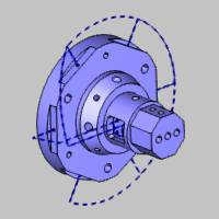
- Radius
This parameter defines the radius, or half the diameter, of the cylindrical retract area.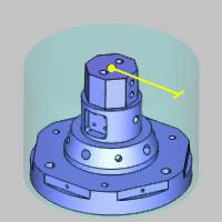
Retract Direction
This option determines how the tool moves to reach the retract area in one of two ways.
- Shortest Distance -
forces the tool to retract to the clearance area directly
or using the shortest distance possible (from the last
tool position of the operation to the clearance area).

- Tool Orientation - forces
the tool to retract to the clearance area following to
tool orientation of the last tool position for the operation.
Axis
This parameter determines the orientation of the cylindrical retract area in relation to the machine setup (machining origin).
- X
Axis - the cylindrical retract area is parallel
to the X-axis.

- Y Axis - the cylindrical retract area is parallel
to the Y-axis direction.

- Z Axis - the cylindrical retract area is parallel
to the Z-axis direction.

- User Defined - allows you to define a custom orientation for the cylindrical retract area. Once this option is selected, the Direction parameter becomes available for you to define the direction.
Direction
The Direction group displays the
direction vector of the selected plane (Axis). When selecting
X Axis, Y Axis, or Z Axis, this in an informational display only.
(For example, when set to Y Axis, the vector displays as X0 Y1
Z0.) When selecting User Defined, you can type values to determine
the custom direction vector, or you can click
to set the direction by selecting a line in the graphics area.
Note: The Direction vector is always in reference to the feature's coordinate system. Generally, this is the Machine Setup (or machining origin), but if the feature is under an index system, then it is in reference to the index coordinate system.
Base Point
This parameter determines an offset of the clearance area in reference to the machine setup (machining origin) along each of the three coordinate axes. This setting is helpful for when the machining origin does not align with the rotational axis of the part.
- X - determines the distance
from the machining origin to the center of the retract
area along the X-axis of the machining origin.
- Y - determines the distance
from the machining origin to the center of the retract
area along the Y-axis of the machining origin.
- Z - determines the distance
from the machining origin to the center of the retract
area along the Z-axis of the machining origin.
-
- click this button to set the Base Point
by selecting geometry in the graphics area.
Tip: When adjusting the Base Point parameter for a cylindrical retract area, generally, you should only need to adjust two of the three values. For example, with a Z Axis cylinder, only the X and Y values need updated to move the base point, and with an X Axis cylinder, you should only adjust the Y and Z values. Adjusting the base point parameter that is the same as the selected Axis does not change the retract area for the cylinder type (the height of the cylinder is essentially infinite).

Angle Step for Rapid Moves
This parameter is the threshold for the maximum segment length (defined by an angle) around the cylinder for rapid moves. Imagine the radius of a cylinder drawn at zero degrees. With an angle step of three degrees, another radius is drawn every three degrees from the starting radius. Each radial line intersects the outside diameter with the distance between each intersecting point defining the segment length.
|
Angle Step = 5 Degrees |
Angle Step = 45 Degrees |

|

|
Group Retracts Dialog
Type
Sphere
Sphere creates a sphere shaped retract
area defined using the following parameters. This retract type
is helpful for multiaxis machining, for example, with parts such
as impellers.
- Radius
This parameter defines the radius, or half the diameter, of the spherical retract area.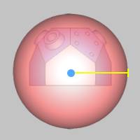
Retract Direction
This option determines how the tool moves to reach the retract area in one of two ways.
- Shortest Distance -
forces the tool to retract to the clearance area directly
or using the shortest distance possible (from the last
tool position of the operation to the clearance area).
- Tool Orientation - forces
the tool to retract to the clearance area following to
tool orientation of the last tool position for the operation.
Base Point
This parameter determines an offset of the clearance area in reference to the machine setup (machining origin) along each of the three coordinate axes. This setting is helpful for when the machining origin does not align with the rotation axis of the part.
- X - determines the distance
from the machining origin to the center of the retract
area along the X-axis of the machining origin.
- Y - determines the distance
from the machining origin to the center of the retract
area along the Y-axis of the machining origin.

- Z - determines the distance
from the machining origin to the center of the retract
area along the Z-axis of the machining origin.
-
- click this button to set the Base Point
by selecting geometry in the graphics area.
Tip: When adjusting the Base Point parameter for a cylindrical retract area, generally, you should only need to adjust two of the three values. For example, with a Z Axis cylinder, only the X and Y values need updated to move the base point, and with an X Axis cylinder, you should only adjust the Y and Z values. Adjusting the base point parameter that is the same as the selected Axis does not change the retract area for the cylinder type (the height of the cylinder is essentially infinite).
Angle Step for Rapid Moves
This parameter is the threshold for the maximum segment length (defined by an angle) around the cylinder for rapid moves. Imagine the radius of a cylinder drawn at zero degrees. With an angle step of three degrees, another radius is drawn every three degrees from the starting radius. Each radial line intersects the outside diameter with the distance between each intersecting point defining the segment length.
|
Angle Step = 5 Degrees |
Angle Step = 45 Degrees |
|
|
|
-
Rapid Plane - is the height at which the tool can rapid safely within a single machining operation. This value is incremental from the Top of Feature setting in the CAM wizard.
-
Feed Plane - is the height at which the tool movement changes from rapid to feedrate. This value is incremental from the toolpath.
- Apply Material Approach to All - displays at the bottom of the wizard when you have selected more than one hole diameter for the feature. This button allows you to apply the Material Approach settings to all features in the wizard tree.
Feature Parameters
- Counterbore Diameter - lists the current value for the counterbore diameter.
- Diameter - lists the current value for
the hole diameter of the feature.
Parameters
Hole Type
-
 Through -creates a through hole using the
Length Through Cut parameter of the Cutting Condition dialog box.
Through -creates a through hole using the
Length Through Cut parameter of the Cutting Condition dialog box. -
Blind -
creates a blind hole.
Thread Type - lists the current Thread Type associated to the feature. Selecting Thread Type will launch the Thread Type dialog box which allows you to select from the Thread Types and Thread Sizes currently in your Thread Library.
Thread Direction
-
 Right Hand -
the software uses the canned cycle configured in the post processor
for a right-hand tap.
Right Hand -
the software uses the canned cycle configured in the post processor
for a right-hand tap. -
Left Hand
- the software uses the canned cycle configured in the post processor
for a left-hand tap.
Hole Groups
Hole Groups are created based on similar diameters who share the same
Top of Feature and Feature Depth. ![]() Click here to expand on
the subject of Hole Groups.
Click here to expand on
the subject of Hole Groups.
|
This section explains Hole Groups and how to define their parameters in the Mill Wizards for all Mill Hole drilling features. This information applies to standard, multiaxis, and cross drilling (Mill Turn). What is a Hole Group?A Hole Group can be one or more holes that share three parameters: Diameter, Top of Feature, and Feature Depth. All holes that you select for a feature that share these parameters are automatically placed into a single Hole Group. Read the following section for further hole group requirements for each drilling type.
Standard Drilling The following images show a standard drilling part with holes at three different levels on the model and two hole diameters. The hole groups for this part are shown with the same color.
Notice the holes that share the same diameter, top of feature, and feature depth have the same color. The software automatically creates the Hole Groups as shown after selecting all of the holes for a single drilling feature.
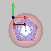
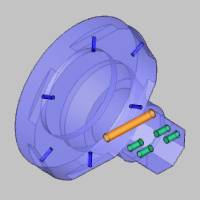
Multiaxis Drilling In addition to the three shared parameters, multiaxis drilling groups must also share the same tool orientation (tool vector) in order to be grouped.
The following images show a multiaxis drilling part with two hole diameters and five different tool orientations. The hole groups for this part are shown with the same color.
Notice that even though the three larger holes on top have the same diameter, depth, and top of feature, these holes cannot be in a single hole group because they don't share the same tool orientation (tool vector). This is also true for the two sets of smaller holes on the opposing faces, except that they do create two hole groups (shown in blue and green), one for each tool vector.
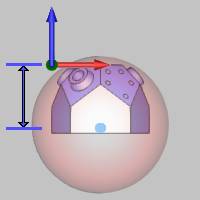
Cross Drilling Cross drilling hole groups require the same three shared parameters, but the exception here is that the tool orientation/rotation angle does not affect the grouping of holes as it does in multiaxis drilling.
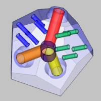
The following images show a part with all cross drill style holes at various locations around the model. There are two hole diameters with holes that share the same top of feature and feature depth. The holes groups created from this part are shown with the same color.
Why Use Hole Groups?Hole groups allow you to define more than one depth for drilling within a single feature. A single hole feature can have one or more hole groups so you can optimize the hole features that you create and eliminate the need for extra features. Hole groups also provide more clearance options, or Group Retracts, to handle the rapid movements between hole groups. Modifying Hole Groups - Feature SettingsThe following information explains the use of hole groups in the Feature page of all Mill Hole Wizards. Using the Hole Groups TableThe Hole Groups section of the Feature settings provides a table for editing Hole Groups and their parameters. You can set the Top of Feature and Feature Depth by typing the values or selecting geometry. You can also break hole groups into separate groups and then regroup them as needed, for example, to modify the rapid movement between holes.
Important: All of the values that display in the Hole Groups table (except Number) can be editing by clicking that item in the table and typing the new value or name. The buttons next to the Hole Groups table are used with the Hole Groups that are selected in the table. When you click a Hole Group in the table, a preview of the holes displays inside the dialog box to help you visualize the parameters for that group.
Number Each hole group is given a number as a reference to the group in the table. This number is automatically created and cannot be edited.
Name Hole groups are automatically named in sequential order with the format of name and number (Group 1). Click the name of any hole group in the table to make it available for editing. Type the new name to create a custom name for the group.
Top of Feature The Top of Feature is the top of the hole as an incremental value from the Machine Setup or machining origin location. Click the Top of Feature value in the table to make it available for editing. Type the new value to set the top of feature for the hole group. After selecting a group in the list, you can use the Pick Top button to set the value using geometry selection.
Important: For multiaxis drilling, the Top of Feature is in reference to the selected geometry, not the machining origin. For cross drilling, the Top of Feature is a radial distance from the center of the part (or the Z-axis of the machining origin for Mill Turn jobs).
Feature Depth The Feature Depth is the depth of the hole as a positive incremental value from the Top of Feature. You can click the value in the table to make it available for editing. Type the new value to set the Feature Depth. You can also use the Pick Bottom button to set the value using geometry selection (after selecting a group in the list). Be sure to properly set the Top of Feature before selecting the Feature Depth.
Tip: For cross drilling (Mill Turn), the Top of Feature and Feature Depth values are calculated as a radial distance from the rotation axis/machining origin. Selecting cylindrical surfaces allows the software to properly calculate both of these values. When using any other geometry type, if the hole extends past the center of the part, you may need to manually type the appropriate Top of Feature and/or Feature Depth value instead of using Pick Top or Pick Bottom.
Counterbore Depth The Counterbore Depth is the depth of the larger hole for counterbore holes. This is a positive incremental value from the Top of Feature. Click the Counterbore Depth value in the table to make it available for editing. After selecting a group in the list, you can use the Pick Counterbore Depth button to set the value using geometry selection.
Break Hole Group The Break Hole Group button breaks the selected Hole Groups into separate single-hole groups. This can only be used when there is more than one hole in the group. Each resulting hole group contains a single hole and the naming follows that of the original group in the format: previous group name, period, new group number (Group 1.1, Group 1.2).
Regroup Holes The Regroup Holes button takes all selected Hole Groups from the list and makes a single hole group. The naming of the new group follows that of the hole group with the lowest number.
Important: In order to regroup holes, the groups that you select must share the same Top of Feature and Feature Depth. Edit these values in the table to be the same for all holes that you want to regroup before clicking Regroup Holes. Note that for multiaxis drilling, holes must also share the same tool orientation or direction vector in order to be grouped.
Pick Top The Pick Top button is used to set the Top of Feature value by selecting geometry such as a point, snap point, or surface edge. Select a Hole Group in the list before clicking Pick Top, or if you don't select a group, you can set the Top of Feature for all groups.
Pick Bottom The Pick Bottom button is used to set the Feature Depth value by selecting geometry such as a point, snap point, or surface edge. Select a Hole Group in the list before clicking Pick Bottom, or if you don't select a group, you can set the Feature Depth for all groups.
Pick Counterbore Bottom The Pick Counterbore Bottom button is used to set the Counterbore Depth value by selecting geometry such as a point, snap point, or surface edge. Select a Hole Group in the list before clicking Pick Counterbore Bottom, or if you don't select a group, you can set the Counterbore Depth for all groups.
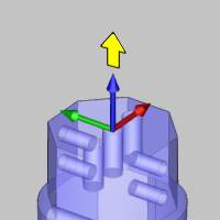
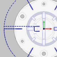
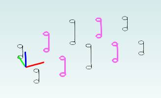
Previewing the Hole GroupsTo make it easier to visualize the parameters you are defining, when you click a group in the Hole Groups table, a preview displays inside the dialog box. The preview displays each hole, the machine setup (machining origin), the feature preview (top, bottom, and diameter), and the workpiece if you have selected one for the job.
View Controls The Hole Groups preview uses the
standard mouse controls for altering the viewing position of the
preview.
Viewing the Workpiece The Hole Groups preview may or may not display the part, based on whether or not you have selected a workpiece for the job. Workpiece selection is the first step of using the Stock Wizard, or it can be assigned (or removed) using the Workpiece item in the CAM Tree. Selecting Multiple Hole GroupsThe Hole Groups table allows for multiple selections using standard controls as follows.
Important: You can click anywhere in the row of a group to select that group in the list. When you click any value other than the number, it becomes available for editing. When adding or removing selections using modifier keys (Ctrl or Shift), select a group by clicking its row under the Number column.
Hole Groups - Operation SettingsWhen you go to the Parameters page for any drilling operation in the Mill Hole Wizards, the Hole Groups section displays the name of each Hole Group in the feature. You then select the group name before setting the effective depth, overall depth, and cycle type settings, such as pecking, for each group.
|
||||||||||||||||||||||||||||||||||||||||||||||||||||||||||||||||||||||||


Break Hole Group
The Break Hole Group button breaks the selected Hole Groups into separate single-hole groups. This can only be used when there is more than one hole in the group. Each resulting hole group contains a single hole and the naming follows that of the original group in the format: previous group name, period, new group number (Group 1.1, Group 1.2).
Regroup Holes
The Regroup Holes button takes all selected Hole Groups from the list and makes a single hole group. The naming of the new group follows that of the hole group with the lowest number.
Important: In order to regroup holes, the groups that you select must share the same Top of Feature and Feature Depth. Edit these values in the table to be the same for all holes that you want to regroup before clicking Regroup Holes. Note that for multiaxis drilling, holes must also share the same tool orientation or direction vector in order to be grouped.
Pick Top
The Pick Top button is used to set the Top of Feature value by selecting geometry such as a point, snap point, or surface edge. Select a Hole Group in the list before clicking Pick Top, or if you don't select a group, you can set the Top of Feature for all groups.
Pick Bottom
The Pick Bottom button is used to set the Feature Depth value by selecting geometry such as a point, snap point, or surface edge. Select a Hole Group in the list before clicking Pick Bottom, or if you don't select a group, you can set the Feature Depth for all groups.
Pick Counterbore Bottom
The Pick Counterbore Bottom button is used to set the Counterbore Depth value by selecting geometry such as a point, snap point, or surface edge. Select a Hole Group in the list before clicking Pick Counterbore Bottom, or if you don't select a group, you can set the Counterbore Depth for all groups.
Next Topic
Clicking Next>> will take you to the Machining Strategy