Direction for One way Machining
Introduction
This topic will explain the direction of One way Machining, will describe where to access it, will provide an example and explain how it works.
One way Machining
There are two main categories for selecting a One-Way machining direction. You can define the direction either dependent on spindle direction or independent of the spindle direction.
Navigation
To access One way Machining in the Mill Multiaxis Wizard:
- In the Sorting group, of the Surface Paths tab, click the down arrow next to Cut order and select One way.
Parameters
To define the moving direction of the tool on the part in relation to the spindle direction, use one of the following options.
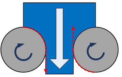
- Climb
- the tool movement and the spindle rotation have the same direction
(tool on left of image).
- Conventional - the tool movement is opposite to the spindle rotation (tool on right of image).
To define the moving direction of the tool on the part independent from the spindle direction, use one of the following options.
- Clockwise
- the tool moves in clockwise direction (left image).
- Counterclockwise - the tool moves in counter-clockwise direction.

Note:
• Direction
for One Way Machiningis
only available with theOne
WayorSpiralcutting method.
• It's
recommended to useEnforce
Cutting Direction (Assume Closed Contours) when you have open contours.
• The
clockwise and counter-clockwise options are not for the spindle rotation.
They are used to determine whether the tool should move around a closed
surface model in clockwise or counter clockwise direction.
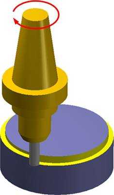
Examples
- The following image
shows a machining where the tool moves counter clockwise while the
spindle is turning clockwise. The tool is always on the right side
of the moving direction.

- The next image shows
that the tool as well as spindle are turning clockwise. The tool is
on the left side of the moving direction.
How it Works
- How
Climb/Conventional Works
Generally the operation only works properly and effectively when you use tool axis control strategy Tool Axis Will be Tilted Relative to Cutting Direction. With other tilt options, it is not possible to clearly define the machining cut direction. The reason for this is the operation decides the cut direction itself. The operation decides between two calculation routines depending only on one factor: the value of the side tilt angle of the cutting direction. - When side
tilt angle is greater than 45 degrees
The machining is recognized as swarf machining. Then the definition of climb or conventional is very easy. The spindle always (except of very few cases) turns clockwise. The tool movement is opposite to the spindle rotation. So you can say that if the tool is on the right side (relative to moving direction of the tool) it always is conventional. When climb milling is set, the tool movement and the spindle rotation have to be in the same direction. The tool always machines on the left side. - When
side tilt angle is less than 45 degrees
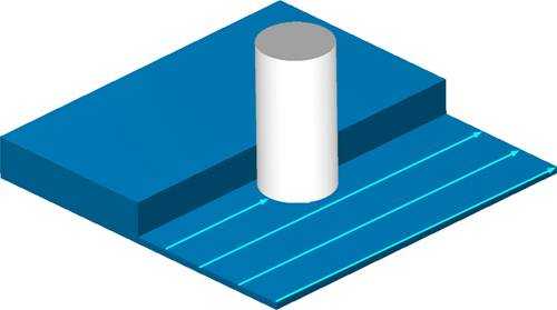
It is a little bit more complicated than swarf milling. Here you don't have a swarf face and you don't work with the side of the tool. You can't define if you are positioned right or left from the contour. Imagine that you are working on a flat face, machining simple parallel cuts. You just don't know where to align the tool because there are no side faces showing where there is material. Nevertheless, the function works as follows: In the flat face example, the paths are parallel to each other: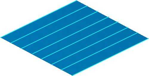
- At first the only information about
any direction is the direction of the cut sequence. The machining
must start from one side.
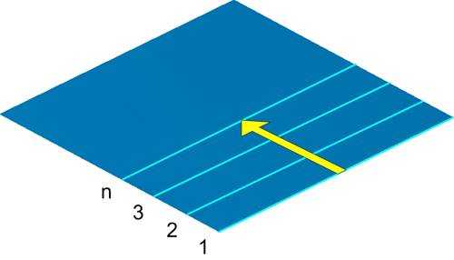
- With this information you know where
there is remaining stock material. With this you also know in which
direction you have to move the tool to get climb or conventional milling.
The following picture shows how a real machining would look. The side
of the material is defined depending on the cut sequence. Since the
spindle always rotates clockwise for a conventional milling as shown
in the picture, the tool has to move from the left to the right.

- How Clockwise and
Counter-clockwise Works
Generally, for Clockwise the tool movement has clockwise direction. For Counterclockwise, the tool movement has counter-clockwise direction. But there are restrictions which you have to consider. The direction can't be clearly defined for every pattern strategy. Most important here is that for all strategies you have to have a closed toolpath. This means that a cut has to end where it starts. Whenever a toolpath is not closed, you can virtually enforce the cutting direction by activating the Enforce Cutting Direction option. The toolpath is not actually closed but internally the calculation assumes a closed contour. - A normal closed
path on a contour.

- Next is an open contour with a
toolpath enforced in its cutting direction.

When you have a closed toolpath
- Parallel
Cuts
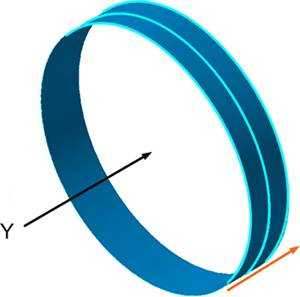
The direction is defined about the view direction onto the first cut. With the function you define two angles which span a plane (parallel cuts). The cuts are parallel to this plane. When you look perpendicular to that plane in the direction where the cuts proceed, you get the cutting direction defined. Both clockwise and counter-clockwise work well with Parallel cuts.
- In the following images, the black
arrows show the view direction. The view direction is defined
by the cut plane and the proceeding direction, which is the orange
arrow.


- In the following images, the black
arrows show the view direction. The view direction is defined
by the cut plane and the proceeding direction, which is the orange
arrow.
- Cuts Along Curve
Here the direction is defined with the curve and the cut planes. Important here is the chaining of the curve, on which side it starts and to where it points. Because this defines the view direction. If you start the chain from the other side, the machining would begin from the other side. WithCuts Along Curve,CwiseandCcwisealways work right.- In the image, the black point
is the start of the chaining of the curve.

- In the image, the black point
is the start of the chaining of the curve.
- Morph Between Two
Curves
Here the direction can't be clearly defined. So setting the direction to clockwise or counterclockwise doesn't always work in this case. This has two reasons: The direction depends of the chaining of the curves. You see that you got two curves and the system doesn't decide which curve shall define the direction because both are weighted the same in the calculation. Also it is not clearly defined which curve is the first and which the second. It is a user choice. You can define the cut proceeding with selecting which curve is the first and which the last, but this has no influence on the direction. - Parallel to Curve
Here the direction will be defined by the curve and the cut sequence direction. Important here is the chaining of the curve, on which side it starts and where it points to. So if in your closed contour the curve points clock wise, setting clockwise lets the tool run clockwise. If the chaining is counterclockwise and you set to clock wise the machining would be counter clockwise. If you set here the direction to counterclockwise the machining would be counterclockwise.- In the following image the cut
sequence is top-down (orange arrow). So the view direction of
the first cut is from the top. In the first image the curve (red)
shows clockwise. In the second image, the curve shows a counter-clockwise
direction. Setting the direction parameter to clockwise, the machining
in the first image is clockwise and in the second image is counterclockwise.


- In the following image the cut
sequence is top-down (orange arrow). So the view direction of
the first cut is from the top. In the first image the curve (red)
shows clockwise. In the second image, the curve shows a counter-clockwise
direction. Setting the direction parameter to clockwise, the machining
in the first image is clockwise and in the second image is counterclockwise.
- Project Curve
Here the direction is defined only by the curve chaining direction. So in closed contour the curve points clockwise, setting clockwise lets the tool run clockwise. If the chaining is counterclockwise, and you select clockwise, the machining is counter-clockwise. If you set the direction to counterclockwise the machining would be counterclockwise. - Morph
Between Two Surfaces
Here the direction can't be clearly defined. So setting the direction to clockwise or counter-clockwise doesn't always work in this case. - Parallel to Surface
Here the direction can't be clearly defined. So setting the direction to clockwise or counter-clockwise doesn't always work in this case.