Multiaxis Gouge Checking
Introduction
The Multiaxis Gouge Check tab allows you to gouge check Drive Surfaces and Check Surfaces against different parts of the tool and tool holder in order to create gouge free toolpaths for complicated surfaces or machining situations. The Drive Surfaces are the machining surfaces or feature geometry. Check Surfaces are any other geometry (or Drive Surfaces) with which you need to avoid collisions. The Gouge check page varies depending on the Toolpath Type in use, and the following sections are organized accordingly.
Wireframe and Surface Toolpaths
You can set up four separate gouge check features each with different ways of handling gouging toolpaths for the selected geometry. There are four main parts to the Gouge Check tab as explained next.
Status
The Status check box is used to turn on or off the gouge check features (1, 2, 3, or 4). Select the check box to turn on the feature, and clear the check box to turn off the feature. Once the Status check box is turned on, the Check section controls what tool parts are gouge checked.
Check
The Check section defines which parts of the tool are gouge checked. The options are as follows: Flute, Shaft, Arbor, and Holder. Once the gouge check is turned on and the tool parts selected, the Strategy and Parameters are selected.
Strategy and Parameters
The Strategy and Parameters section defines how the system handles a gouging toolpath. The system either moves the tool to avoid gouging, removes the gouging toolpath sections, reports the gouging, or stops the calculation altogether. Each strategy has a different set of parameters. Once the strategy is selected, the corresponding parameters become available. Once the Strategy and Parameters section is set up, the Geometry section is all that remains.
The strategies are listed next with links to the topic for each.
-
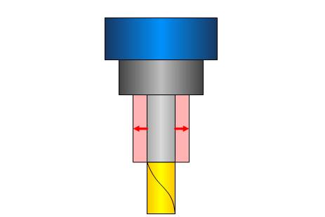
Retract Tool - retracts the tool based on the selected Retract Option to avoid gouging. Click Advanced to open the Advanced Options.
-
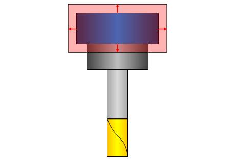
Tilt Tool - uses angle value ranges at which the tool tilts away from potential gouging. You must select a tilting option: Use Lead Angle, Use Side Tilt Angle, or Automatic. Once the tilting option is selected, to access the parameters, click Parameters. Smoothing can be applied to the side tilt angle.
-
Trim and Relink Toolpath - removes the gouging toolpath sections by using the selected parameters option.
-
Stop Toolpath Calculations - ends the toolpath calculation when a gouge occurs. When using this option, as soon as a gouge is detected, the toolpath calculation is stopped to show that a gouge has occurred.
-
Report Collisions - checks for collision between the tool and the check faces without trying to avoid the collision. The result is an informational message reporting any collisions.
Geometry
This Geometry section is used to specify the faces to which the collision control is performed. When using Drive Surfaces, all selected Drive Surfaces are checked. This option makes sure that your drive surface won't be damaged. The collision check tolerance uses the cut tolerance value defined in the feature. When using Check Surfaces, you can set additional surfaces to check against. This might be other surfaces such as fixtures.
-
Drive Surfaces
![]() Select the check box to gouge check all selected Drive Surfaces.
The Stock to Leave and
Tolerance become unavailable.
Select the check box to gouge check all selected Drive Surfaces.
The Stock to Leave and
Tolerance become unavailable.
![]() Clear the check box when not checking all selected Drive Surfaces. The
following two options become available.
Clear the check box when not checking all selected Drive Surfaces. The
following two options become available.
-
Stock to Leave - When not gouge checking the drive surfaces, type a value for the amount of clearance between the tool and check surface.
-
Tolerance - When not gouge checking the drive surfaces, type a value for the accuracy used for gouge checking.
-
Check Surfaces
![]() Select the check box to gouge check surfaces other than the selected drive
surfaces. Click
Select the check box to gouge check surfaces other than the selected drive
surfaces. Click ![]() to
select geometry.
to
select geometry.
![]() Clear the check box when there are no check surfaces to gouge check.
Clear the check box when there are no check surfaces to gouge check.
Note: When using Drive Surfaces, the tolerance as well as the offset to the part are fixed and they can't be changed. When only Check Surfaces is used, you have to set 2 additional parameters: Check Tolerance and Stock to Leave. The Stock to Leave sets a clearance distance between the specified parts of the tool and check surface. The Tolerance sets a check tolerance for the accuracy of the gouge detection.
Other Options
Remaining Collisions
The Remaining Collisions dialog box allows you handle any remaining collisions by specifying an action for contours or link moves separately. You can select to keep the collisions or trim the collisions and re-link the non-gouging paths. These options are used with the Tilt Tool gouge check strategy.
Clearance for Tool Parts
The Tool Clearances dialog box provides the option to define extra tool clearance values that are applied in addition to the selected Gouge Check settings. These values are only used when you turn on at least one gouge check.
Select a Cylindrical or Conical clearance type for the tool. The Clearance Values change depending on the selected Clearance Type. For either selection, type the values to define the amount of clearance for each tool part: Shaft, Arbor, and Holder. You can define an Angular Clearance to create a protected area for the tool as an angle between the drive surface edge and a line drawn from the tool contact point and the point of collision, for example, with the holder.
Advanced
Click Advanced to open the Advanced Parameters for Gouge Checking dialog box.
Multiaxis Roughing Toolpath.
Collision avoidance
![]() Check with machining surfaces - The holder will
not be checked against the in machining surface with this method.
Check with machining surfaces - The holder will
not be checked against the in machining surface with this method.
![]() Check with machining surfaces - This enables the toolpath calculation to gouge
check the tool and holder against the selected geometry.
Check with machining surfaces - This enables the toolpath calculation to gouge
check the tool and holder against the selected geometry.
Tip: This option is best utilized when the selected geometry is not completely inside of the stock material.
![]() Check with in-process stock - The holder will
not be checked against the in process stock.
Check with in-process stock - The holder will
not be checked against the in process stock.
![]() Check with in-process stock - This enables the toolpath calculation to gouge
check the tool and holder against the in process stock.
Check with in-process stock - This enables the toolpath calculation to gouge
check the tool and holder against the in process stock.
Note: In Process Stock is the stock as it would appear at any point in the operation. As the operation is run, material is continuously being removed. As material is being removed, the stock to check against the tool and holder for gouges is continuously being updated. With this method, the Gouge Checks are run as the toolpath is being generated.
Clearance values
Clearance values allow you to specify individual clearance distances to use on the following components:
- Shaft - sets the clearance to use for the shaft.
- Arbor - sets the clearance to use for the arbor.

- Holder - sets the clearance to use for the Holder.
Swarf Machining Toolpath
Gouge Excess
- Check
Guide curves only - ensures there is no collision with the guide curves.
Swarf surfaces - check the chosen surfaces for the SWARF operation. This allows access to the Collision handling options.
Additional surfaces - allows for the selection of additional surfaces to check against.
Swarf & Additional surfaces - checks the surfaces chosen for the SWARF operation, and allows for the selection of additional surfaces to check against.
- Collision handling
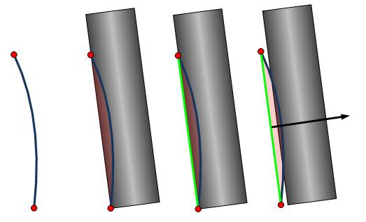
Degouge - The degouging will push the tool out of swarf surface in case a collision occurs. To avoid the collisions the tool will be pushed away orthogonal to the contact line between to the upper and lower curve. The user can select the swarf surfaces or any other surface for the degouging. A tolerance sets the accuracy of the degouging.
Balance - The balancing equalizes the amount of rest material and gouging.
Balance within allowance - While the balancing equalizes the amount of rest material and a gouge, the balancing with allowance will try not to exceed the user defined thresholds. In case a threshold will be exceed a warning will be shown.
- Gouge allowance - allows you to assign an allowance to the gouge.
- Excess material allowance - allows you to assign an allowable amount of excess material.
Avoid by relinking
- Check
- - no check is performed.
Swarf surfaces - check the chosen surfaces for the SWARF operation. This allows access to the Collision handling options.
Additional surfaces - allows for the selection of additional surfaces to check against.
Swarf & Additional surfaces - checks the surfaces chosen for the SWARF operation, and allows for the selection of additional surfaces to check against.
- Check faces clearance - allows for an amount of face clearance to be used on the check surfaces in case of collision.
Avoid by retracting
- Check
- - no check is performed.
Swarf surfaces - check the chosen surfaces for the SWARF operation. This allows access to the Collision handling options.
Additional surfaces - allows for the selection of additional surfaces to check against.
Swarf & Additional surfaces - checks the surfaces chosen for the SWARF operation, and allows for the selection of additional surfaces to check against.
- Direction
Along tool axis - This collision control simply retracts the tool along its tool axis from when a collision is detected. At the colliding area the tool retract along its tool axis. After the collision the tool retracts back to the drive surface.
Along contact line - This option will retract the tool along its contact line with the drive faces. In the colliding area the tool retract along the line to avoid the collision.
Check faces clearance - allows for an amount of face clearance to be used on the check surfaces in case of collision.
Clearances
- Shaft clearance - sets the clearance to use for the shaft.
- Arbor clearance - sets the clearance to use for the arbor.
- Holder clearance - sets the clearance to use for the Holder.