Output format
Introduction
This topic will explain the Output format option, describe where to find it, and provide examples.
Output format
The Output Format controls how the multiaxis toolpath tilting is handled when changing 5-axis toolpaths to 4- or 3-axis output. For 5-axis output there is no limit placed on the tool axis orientation. For 4-axis the tilting is limited by one degree (one rotary axis) and for 3-axis the tilting is limited by 2 degrees (two rotary axes).
Navigation
To access Output format:
- The Output format can be found as the first option in the Tool axis control page.
Options
5 Axis
- Set the Output format to 5 Axis and set all of the parameters as desired.
4 Axis
- Set the Output format to 4 Axis and select the Rotary axis button.
The 4th axis dialog appears:
4th Axis
- Direction - select the rotary axis:
- X-axis
- Y-axis
- Z-axis
- User
defined axis
- With User defined axis selected, click
 to open the Line dialog box. You can type coordinate values, or
click Pick to select geometry.
to open the Line dialog box. You can type coordinate values, or
click Pick to select geometry.
- With User defined axis selected, click
- Point
Tool to Rotary Axis
-
 Select the check box to force
the tool to point to the rotary axis. Lead angle tilting is no
longer available.
Select the check box to force
the tool to point to the rotary axis. Lead angle tilting is no
longer available. Clear the check box
to turn off this option.
Clear the check box
to turn off this option.
5th Axis
- Lock at Angle - type an angle
value at which to lock the 5th axis. This can be used for 4th
axis machines with fixed-tilt heads, or for locking the fifth
axis of a 5-axis machine.
- Relative to Cutting Direction - is only used when the tool axis points through the rotation axis. This provides constant 4-axis machining while tilting relative to the cutting direction.
3 Axis
- Set the Output format to 3 Axis and select the ... button.
The Tool plane direction for 3 axis dialog appears:- Top - leaved the tool parallel to the Z axis.
- Other direction - allows you to define the tool vector by entering its X, Y, and Z, values, or by using the Select tool plane button to pick a line whose vector the tool should be parallel with.
- Top - leaved the tool parallel to the Z axis.
Examples
This parameter sets the output to 4- or 5-axis. The output for 5-axis uses complete freedom of the tilt range. For 4-axis this freedom is limited by 1 degree. So for 4-axis output a portion of the 5th axis is projected back onto the selected 4th axis. Interesting here is the influence on the behavior of the tool contact point.
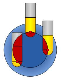
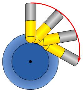
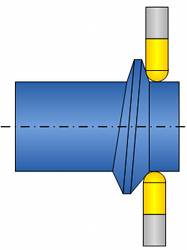
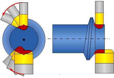
The following descriptions are related to the examples in the next images. The tool is performing a flank milling around that cylinder, along the wall. The tilt angle on the wall changes as it goes around the cylinder. The toolpath pattern is Parallel to Surface. The drive surface is the wall, the guiding surface the floor (cylinder).
5-Axis Output Format
-
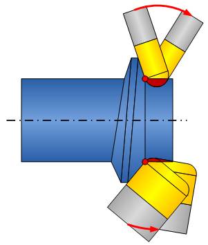
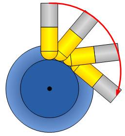
Tilting - for the 5-axis output no axis limitation is set on the tool tilting. That means that the tool can tilt sideways (left image) and lead tilt (right image) as it goes around the wall.
Contact Point
-
On the Drive Surface - is always fixed. It always is positioned close to the drive surfaces edge.
-
On the Tool - for ball-mill tools as well as bull-mill tools it is always on the radius of the tip. For flat-end tools it is on the edge.
For the side-tilt direction (left image) and the lead-tilt direction (right image) the tool always rotates around the surface contact point (red dots). You can see that in this example the ball-mill tool gouges because of the tight surface contact point between the wall and the cylinder floor surface. This won't be compensated automatically so gouge checking is necessary.
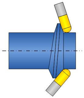
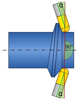
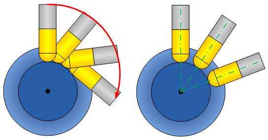
4-Axis Output Format
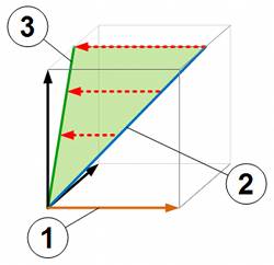
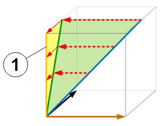
Tilting - the images show the progression: 5-axis, projection of 5th axis, and 4-axis.
-
When using only 4-axes then the 5th component of tool-axis vector (2) is projected onto the plane (3) of the of the 4th-axis (1).
-
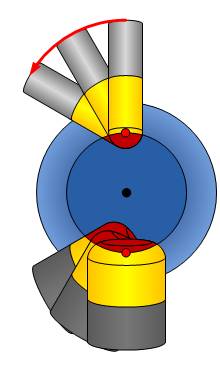
While for 5-axis output the side tilt constantly changes, in 4-axis the side tilt angle is fixed. Flank milling is not possible anymore for this part.
-
While the side tilt is fixed, the tool is still able to tilt in the 4th-axis lead and lag direction.
-
Lock the Fifth Axis At - sometimes, the 4-axis machines have a fixed-tilt head mounted, like a 45-degree head. In this case the spindle direction is, for example, tilted 45 degrees to the rotary-axis vector. Then the locked axis value must be set to 45 degrees. The 45 degree angle means that the vector, from the tool tip towards the spindle direction, and the rotary axis vector [for example, X-axis vector which is (1,0,0)] both have a 45 degree angle to each other. Another usage of this parameter is in combination with a 5-axis machine. In order to reduce rotary-axis motion it might be desired to use a 5-axis machine, but still set the toolpath output to 4-axis with a fixed 5th axis angle. This means that one of the rotary-axes is fixed for the entire toolpath.
-
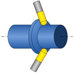
Point Tool to Rotary Axis - here the tool is forced to tilt through the rotary axis (right image) and can no longer tilt in lead/lag direction.
-
Relative to Cutting Direction - is only used when the tool axis points through the rotation axis. This provides constant 4-axis machining while tilting relative to the cutting direction. The following animation provides an example.
Contact Point
-
On the Drive Surface - is always fixed. It always is positioned close to the drive surfaces edge.
-
On the Tool - for ball-mill tools as well as bull-mill tools it is always on the radius of the tip. For flat-end tools it is on the edge.
You can see that for the (now fixed) side-tilt direction (right image) and the lead-tilt direction (left image) the tool always rotates around the surface contact point (red dots). You also see that in this example the ball-mill tool gouges because of the tight surface contact point between the wall and the cylinder floor surface. This won't be compensated automatically so gouge checking is necessary.
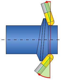
3-Axis Output
For 3-axis output there is no tool tilting possible. In this case the 5th axis tilting is projected onto the 4th axis which is then projected onto the main spindle direction. This is shown in the following image. The result is a fixed tool axis orientation.
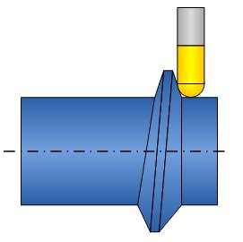
For the example used in this help topic as shown, 3-axis machining can't reach the entire part because the tool axis is always the main spindle direction.