Stock Specification
Introduction
The purpose of this topic to explain all the options found in the Stock Specification dialog, which will allow you to define the shape, size and orientation of the stock.
When the Stock Specification
dialog
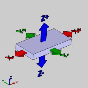
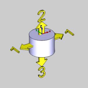
box is open, a ![]() coordinate system
gnomon displays to show the stock Origin, which is located at the top
and center of the stock. The stock origin is only
used as the reference when changing the stock size and orientation, when
applicable. The stock origin is not
related to the machining origin in the Machine Setup.
coordinate system
gnomon displays to show the stock Origin, which is located at the top
and center of the stock. The stock origin is only
used as the reference when changing the stock size and orientation, when
applicable. The stock origin is not
related to the machining origin in the Machine Setup.
Stock Type
The first step is to define the overall shape of the stock by selecting the Stock Type. All definitions are explained in this topic. To jump to a particular stock types definition, click the associated icon in the table below.
|
|
Rectangle |
Cylinder |
Wireframe |
Solid |
STL |
Revolve |
|
Active |
|
|
|
|
|
|
 Rectangle
Creates a cubic stock.
Size
-
 Bounding Box - sets the stock size using the extents
of the part geometry. The bounding stock is created using one of the
two following Geometry Options.
Bounding Box - sets the stock size using the extents
of the part geometry. The bounding stock is created using one of the
two following Geometry Options.
Geometry Options -
Auto from Workspace - automatically
sets the stock size using all geometry that is currently in the
graphics area. If solid and wireframe geometry exist, only the
solid is used to create the bounding box.
-
 Pick
- is used to manually select geometry to define the bounding box. When the
Pick option is selected, the selected items
box lists all of the selected entities.
Pick
- is used to manually select geometry to define the bounding box. When the
Pick option is selected, the selected items
box lists all of the selected entities.-
 - when
Pick is selected, the selected geometry displays in the Selected Items
list.
- when
Pick is selected, the selected geometry displays in the Selected Items
list. -
Calculate Stock - is used to confirm the geometry selection and create the stock when using Pick.
-
-
Enter - allows you to type values for the stock
size as follows.
-
 Length (X)
- is the stock length along the X-axis.
Length (X)
- is the stock length along the X-axis. -
 Width (Y)
- is the stock width along the Y-axis.
Width (Y)
- is the stock width along the Y-axis. -
 Height (Z)
- is the stock height along the Z-axis.
Height (Z)
- is the stock height along the Z-axis.
Stock Orientation
This group defines where the stock is located in the graphics area. When the stock geometry is defined, the stock origin is automatically placed at the top and center of the stock.
To make all of the orientation options available, in the Size group, click Enter.
-
Pick Origin - is used to select geometry in the graphics area as the stock origin.
-
-
 - click in
this box to select a vertex as the origin. The selected vertex/point
is listed here.
- click in
this box to select a vertex as the origin. The selected vertex/point
is listed here.
-
-
Enter Origin - allows you to type coordinate values for the stock origin.
-
-
 - sets the X-axis value.
 -
 - sets the Y-axis value.
 -
 - sets the Z-axis value.
-
-
X Axis - this allows you to select geometry that defines the direction for the X Axis.
-
-
 Reverse Direction
- reverses the current X-axis direction.
Reverse Direction
- reverses the current X-axis direction.
-
-
Y Axis - this allows you to select geometry that defines the direction for the Y Axis.
-
-
Reverse
Direction - reverses the selected Y-axis direction.
-
-
Z Axis - this allows you to select geometry that defines the direction for the Z Axis.
-
-
Reverse
Direction - reverses the selected Z-axis direction.
-
Note: When using the Stock Wizard, the Enter boxes display the current size and origin location of the stock.
Offset
This group is used to extend or trim the stock geometry along any of the Cartesian axes. You can type positive or negative values to extend or trim the stock respectively in each direction.
| Offset Diagram | |
|
|
 Cylinder
Creates a cylindrical stock.
Size
-
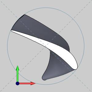
Bounding Box - sets the stock by using the extents of the selected Geometry Option to create a bounding box that will center the stock. The diameter of the stock is then equal to the longest side of the rectangular bounding box.

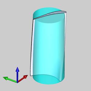
Note: While the default Bounding Box option works fine in most cases, the image above shows a scenario in which it fails to enclose all of the geometry in the cylindrical stock. The Bounding Box is shown with dotted lines. Notice that the Bounding Box itself encloses the geometry, while the arc that is created fails to.
-
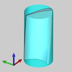
Bounding Cylinder - uses an algorithm to calculate the smallest possible cylinder to enclose the geometry selected with the Geometry Option to create stock.
Geometry Options:
-
Auto from Workspace - automatically sets the stock size using all geometry that is currently in the graphics area. If solid and wireframe geometry exist, only the solid is used to create the bounding box.
-
Pick - is used to manually select geometry to define the stock size. When the Pick option is selected, the selected items box lists all of the selected entities.
-
Enter - allow you to type values for the stock size as follows:
-
-
 Diameter
- is the diameter of the cylindrical stock.
Diameter
- is the diameter of the cylindrical stock. -
 Height
- is the height of the cylindrical stock.
Height
- is the height of the cylindrical stock.
-
Stock Orientation
This group defines where the stock is located in the graphics area. When the stock geometry is defined, the stock origin is automatically placed at the top and center of the stock.
To make all of the orientation options available, in the Size group, select Enter.
-
Pick Origin - is used to select geometry in the graphics area as the stock origin.
-
-
- click in
this box to select a vertex as the origin. The selected vertex/point
is listed here.
-
-
Enter Origin - allows you to type coordinate values for the stock origin.
-
-
- sets the X-axis value.
-
- sets the Y-axis value.
-
- sets the Z-axis value.
-
-
X Axis - this allows you to select geometry that defines the direction for the X Axis.
-
-
Reverse Direction
- reverses the current X-axis direction.
-
-
Y Axis - this allows you to select geometry that defines the direction for the Y Axis.
-
-
Reverse
Direction - reverses the selected Y-axis direction.
-
-
Z Axis - this allows you to select geometry that defines the direction for the Z Axis.
-
-
Reverse
Direction - reverses the selected Z-axis direction.
-
Note: When using the Stock Wizard, the Enter boxes always display the current size and origin location of the stock.
Offset
This group is used to extend or trim the cylindrical stock geometry. You can type positive or negative values to extend or trim the stock respectively in three directions.
|
Offset Diagram |
|
|
|
 Wireframe
Creates a custom shaped stock by extruding 2D geometry.
Size
-
Pick Geometry - is used to manually select geometry to define the stock size. To enable selection mode, click Pick Geometry. Select the appropriate wireframe geometry from the graphics area, and then click
 OK.
OK. -
Top of Stock- is the top of the stock from the WCS (or world coordinate system at X0Z0Y0). You can type a value in the Top of Stock box, or you can click Pick to enable selection mode and select geometry from the graphics area to define the Top of Stock value.
-
Height - defines the height of the extruded stock from the Top of Stock value.
Stock Orientation
This group defines where the stock is located in the graphics area. When the stock geometry is defined, the stock origin is automatically placed at the top and center of the stock.
-
Extrusion Direction - defines the direction in which the cylinder is extruded. Select X Axis, Y Axis, or Z Axis.
-
X Axis - enables you to select geometry to define the X Axis direction. Click in the X Axis box and then select geometry.
-
 Reverse Direction - reverses the current X-axis direction.
 -
Y Axis - enables you to select geometry to define the Y Axis direction. Click in the Y Axis box and then select geometry.
-
Reverse
Direction - reverses the current Y-axis direction.
-
Z Axis - enables you to select geometry to define the Z Axis direction. Click in the Z Axis box and then select geometry.
-
Reverse
Direction - reverses the current Z-axis direction.
 Solid Body
Creates stock from a solid body in the graphics area.
-
Solid Body - is
used to select a solid body to define the stock. The selected geometry
displays in the Solid Body box.
- Calculate Stock- is used to confirm the geometry selection and creates the stock after selecting a solid body.

 STL
STL
Creates stock from an .stl file.
-
Browse - displays the Open dialog box for you to locate and open an .stl file which is used to create the stock geometry. There is an informational display to show the file name of the file currently in use.
STL File Unit
-
When the dialog opens you will be able to select the unit type in which the .stl file was created: millimeter or inch.
 Revolve
Creates custom stock by revolving sketch geometry.
Stock Coordinate System
When creating revolved stock, you must assign a SolidWorks coordinate system that you want to use for the stock creation. This coordinate system is then used for the parameters that you define to create the stock (size and location). Generally, you should make this the same as the machining origin coordinate system. (This also saves you time by eliminating the need to create another SolidWorks coordinate system for the machining origin in the Machine Setup.)
Important: The sketch geometry is revolved around the Z-axis of the coordinate system you create. After selecting the sketch, click Calculate Stock to view the result.
 Size
Size
The size of custom stock is defined by revolving sketch geometry that you have already created. After assigning the coordinate system for the stock geometry, click in the Size box, select the geometry to revolve, and click Calculate to create the stock preview in the graphics area.
- Calculate Stock - is used to confirm the geometry selection and create the stock after selecting a profile.
Note: The following values can be altered after selecting geometry and clicking Calculate. When you change these values, the stock preview is not updated in the graphics area, but the values are saved and automatically loaded in the Feature parameters of the wizard.
-
(Stock Diameter)
- displays the outside diameter of the stock.
-
 (Internal Diameter)
- displays the inside diameter of the stock.
(Internal Diameter)
- displays the inside diameter of the stock. -
(Length)
- displays the length of the stock along the lathe Z-axis.
Once the Stock Orientation is defined, click
![]()
![]() next to go to the
Machine Setup.
next to go to the
Machine Setup.
Related Topics
The Stock Wizard and Machine Setup Tutorials
Next Topic
After setting
the stock size in the Stock Definition, click ![]()
![]() (next) to go to the Machine Setup.
(next) to go to the Machine Setup.