Mill Turn Tool Crib Mounting Parameters
Mounting
The Mounting group of the tool crib contains all of the parameters for modifying the orientation of adapters and tools when mounting them to the tool devices of the machine (milling spindles or turrets). The parameters that display change based on the item currently selected in the device tree (or tools list). The parameters are explained separately for adapters, milling tools, or turning tools.
Tip: The Mounting parameters are unavailable until you select either an adapter or a tool in the device tree or the tools list. After selecting an adapter or tool, you can then modify its mounting orientation with the parameters explained next.
Adapter Mounting Parameters
When mounting an adapter to a tool device, you align the adapter's mounting coordinate system to the mounting coordinate system of the tool device station or substation. Tool adapters are mounted to a station before mounting a tool to the adapter. The mounting parameters for an adapter are explained next.
Mounting
-
Substation
A substation is one of the mounting locations of any turret station. (Milling Spindle stations do not have substations.) For example, a turret may have one or more mounting locations defined for each station, such as front, side, and/or back. The Substation list displays all mounting locations that are available for the selected station. After adding or mounting an adapter to a station, click the Substation down arrow to select the desired substation for the adapter.
-
Align Adapter X
This parameter allows you to modify the mounting orientation of an adapter by realigning X-axis of the adapter's coordinate system to any axis direction of the mounting location's coordinate system. Click the Align Adapter X down arrow to select a new alignment direction: X, -X, Y, -Y, Z, -Z, or User Defined. When User Defined is selected, the X, Y, and Z values become available for you to type a custom direction vector to align the adapter axis.
-
Align Adapter Z
This parameter allows you to modify the mounting orientation of an adapter by realigning Z-axis of the adapter's coordinate system to any axis direction of the mounting location's coordinate system. Click the Align Adapter Z down arrow to select a new alignment direction: X, -X, Y, -Y, Z, -Z, or User Defined. When User Defined is selected, the X, Y, and Z values become available for you to type a custom direction vector to align the adapter axis.
-
Shift
The Shift values are used to move the adapter linearly along the mounting location's coordinate system. Type a value in the X, Y, or Z boxes to shift the adapter's location along that axis.
-
Rotation
The rotation axis and angle parameters are used to rotate the adapter in reference to the mounting location's coordinate system. Click the Axis down arrow to select the X, Y, or Z axis (of the substation) around which you want to rotate the adapter. Type a positive or negative value in the Angle box to determine the amount of rotation around the selected rotation axis.
Milling Tool Mounting Parameters
The mounting parameters are used to properly align milling tools to either a tool device station, substation, or a tool adapter as explained next. When mounting a tool to an adapter that contains more than one tool mounting point (TMP) defined, you must also select the appropriate TMP on the adapter.
Mounting
-
Substation
A substation is one of the mounting locations of any turret station. (Milling Spindle stations do not have substations.) For example, a turret may have one or more mounting locations defined for each station, such as front, side, and/or back. The Substation list displays all mounting locations that are available for the selected station. After mounting a milling tool to a turret station, click the Substation down arrow to select the desired substation for the tool, as needed.
- Adapter Station
The Adapter Station list is used when there is more than one tool mounting point (TMP) defined for a tool adapter. When mounting a milling tool to an adapter that has more than one TMP defined, click the Adapter Station down arrow, and select the appropriate TMP to which you want to mount the tool.
-
Mounting Orientation
The Mounting Orientation group is used to modify the orientation of a tool that is mounted to a device station or tool adapter in reference to the selected mounting location's coordinate system. You can use one of four predefined orientations as follows.

-
1 - aligns the tool to the negative Z-axis direction of the mounting location's coordinate system (station or adapter).
-
2 - aligns the tool to the negative X-axis direction of the mounting location's coordinate system.
-
3 - aligns the tool to the positive Z-axis direction of the mounting location's coordinate system.
-
4 - aligns the tool to the positive X-axis direction of the mounting location's coordinate system.
Note: The Mounting Orientation options in the tool crib are used to properly orient the tool for posting and simulation (this orientation isn't used for the toolpath calculation). The mounting orientation number used is not critical, meaning as long as the tool displays in the proper orientation in the preview window, then the correct setting is selected. The correct orientation must be defined to create proper posting and simulation.
-
Shift
The Shift values are used to move the tool linearly along the mounting location's coordinate system. Type a positive or negative value in the X, Y, or Z boxes to shift the tool's location along that axis.
-
Rotation
The Rotation parameter is used to rotate the tool in reference to the mounting location's coordinate system. Type a positive or negative value in the Angle box to determine the amount of rotation around the Y-axis of the tool's mounting location coordinate system. (You should use the Mounting Orientation parameters before modifying the rotation angle, which is designed for special case scenarios.)
Turning Tool Mounting Parameters
The mounting parameters are used to properly align turning tools to either a tool device station, substation, or a tool adapter as explained next. When mounting a tool to an adapter that contains more than one tool mounting point (TMP) defined, you must also select the appropriate TMP on the adapter.
Mounting
-
Substation
A substation is one of the mounting locations of any turret station. (Milling Spindle stations do not have substations.) For example, a turret may have one or more mounting locations defined for each station, such as front, side, and/or back. The Substation list displays all mounting locations that are available for the selected station. After mounting a turning tool to a turret station, click the Substation down arrow to select the desired substation for the tool, as needed.
- Adapter Station
The Adapter Station list is used when there is more than one tool mounting point (TMP) defined for a tool adapter. When mounting a turning tool to an adapter that has more than one TMP defined, click the Adapter Station down arrow, and select the appropriate TMP to which you want to mount the tool.
-
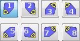
Mounting Orientation
The Mounting Orientation group is used to modify the orientation of a tool that is mounted to a device station or tool adapter in reference to the selected mounting location's coordinate system. You can use one of eight predefined orientations as follows.
 The Reverse button is used to
swap the extrusion direction of a lathe tool holder/insert. This leaves
the tool in its current mounting orientation, changing on which side of
the holder the insert is located.
The Reverse button is used to
swap the extrusion direction of a lathe tool holder/insert. This leaves
the tool in its current mounting orientation, changing on which side of
the holder the insert is located.
Important: The Mounting Orientation options in the tool crib are not necessarily the same as the orientation number in the tool page of the Lathe Wizard. It is important to select the proper insert orientation in the tool page for the toolpath calculation and posting. The Mounting Orientation that you select for a tool in the tool crib must be properly set for posting and simulation purposes. As long as the tool is properly oriented in the preview window of the tool crib, then the proper Mounting Orientation is selected.
For more information, view the Turning Tool Mounting Orientation Reference Guide.
-
Shift
The Shift values are used to move the tool linearly along the mounting location's coordinate system. Type a positive or negative value in the X, Y, or Z boxes to shift the tool's location along that axis.
-
Rotation
The Rotation parameter is used to rotate the tool in reference to the mounting location's coordinate system. Type a positive or negative value in the Angle box to determine the amount of rotation around the Y-axis of the tool's mounting location coordinate system. (You should use the Mounting Orientation parameters before modifying the rotation angle, which is designed for special case scenarios.)
Examples
For more information, view Modifying Mounting Parameters Examples.