dModifying Mounting Parameters Examples
Introduction
This topic illustrates how to use the mounting parameters for tools and adapters in the Mill Turn Tool Crib. This topic is supplemental to the Mill Turn Tool Crib Mounting Parameters topic.
Selecting a Station (Milling Spindles)
When you add or mount a tool or adapter to a milling spindle device, you select the Station Number in the Mounting Location dialog box. (The station number displays in the device tree as well as in the Mounting group next to Station, but the number is not available for editing in this location.)
-
To add stations to a milling spindle device, do one of the following:
- Right-click the device name in the device tree, and click Add Adapter or Add Tool.
- Click to select the device name in the device tree, and click Add From Tool Library or Add From Tool Adapter.
- Right-click a tool or adapter under Loose tools or the tool Shelf, and click Mount.
The Mounting Location dialog box displays.
-
Next to Station, click the down arrow and select the number that corresponds to the tool changer station in which the tool and/or adapter your are mounting resides.
If you have added an adapter, select the Substation to which the tool is mounted, and click OK. -
A station is added to the milling spindle device tree.
Selecting the Substation (Turrets)
This section describes selecting a substation (one of the mounting locations of a turret station) when mounting an adapter or tool to a turret type tool device. This information does not apply to milling spindles/heads as they do not contain substations, but rather one or more tool changer stations.
-
When you mount an adapter or tool to the station of a tool device, it is automatically selected in the device tree, which makes its Mounting parameters available for editing. (Otherwise, select an adapter or tool in the device tree to make the Mounting parameters available.)
-
The station of a tool device may have one or more mounting locations defined (substations). When there is more than one mounting location, you must select the appropriate Substation to which the adapter is mounted.
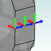
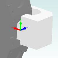
The following image shows an example of three substations defined for station 1: Front, Side, and Back.
|
Substations (Turret Mounting Locations) |
|
The following table shows the mounting location/reference
points for adapters, lathe tools, and mill tools. Note that adapter mounting
locations are user-defined meaning you can create them to your preference.
|
Adapter Mounting Reference |
Mill Tool Mounting Reference |
|
|
|
|
When mounting tools or adapters, their reference
point is matched to the selected mounting location's coordinate system.
|
|
|
|
When you mount an adapter or tool to a station, the first available substation is automatically selected.
Substation 1.Front
-
Click the down arrow next to Substation, and select the appropriate mounting location to which you want to mount the adapter, for example, 5.Sideface.
Substation 1.Side
The Substation list dynamically updates to
show only the available mounting locations for the selected station. Substations
do not display in the list if they do not exist in the turret definition
or if a tool or adapter is already mounted to it.
-
You can now modify the remaining mounting parameters as explained in the following sections of this document.
Selecting an Adapter Station
Tool adapters may have one or more tool mounting points (TMP). When you mount a mill or lathe tool to an adapter, if there is more than one TMP, you must select the appropriate adapter station (TMP) to which the tool is mounted.
-
Add or select a mounted tool in the device tree or tools list to make its mounting parameters available.
-
Next to Adapter Substation, click the down arrow, and select the appropriate TMP to which the tool is mounted.
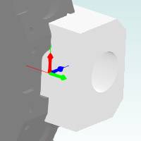
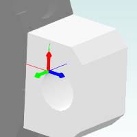
|
Tool on Substation 1 |
Tool on Substation 2 |
|
|
|
Tool on Substation 1 |
Tool on Substation 2 |
|
|
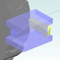
Tip: When mounting a tool, it can be helpful to make the adapter or device transparent so that it is easier to see the tool in its initial orientation (before you change the mounting parameters). Right-click anywhere in the preview window to access a shortcut menu with viewing options, hide and transparent.
-
You can now update the mounting parameters as needed. (The remaining mounting parameters are explained in the following sections of this document.)
Tip - Viewing Adapter Tool Mounting Points
If you need to verify the tool mounting points and the coordinate systems that define them, you can open the Tool Adapter Definition dialog box while adding the adapter to view the tool mounting points (TMP).
-
After clicking Add Adapter or Add From Adapter Library, you can double-click any adapter in the Adapter Library to open the Tool Adapter Definition dialog box.
-
You can use the preview window of the Tool Adapter Definition to view the tool mounting points and their coordinate systems for the selected adapter.
-
Close the Tool Adapter Definition dialog box to return to the Adapter Library and select the desired adapter.
-
Click OK to add the selected adapter to the Tool Crib.
Modifying the Adapter Orientation (Coordinate System Alignment)
The mounting parameters allow you to realign adapters in reference to the mounting location coordinate system as explained next. This allows you to change the orientation defined for an adapter in the Adapter Library, so that it can be used for other orientations.
-
The Align Adapter X and Align Adapter Z parameters are used to modify the orientation of an adapter in reference to the coordinate system of the station (milling spindles/heads) or substation (turrets).
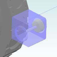
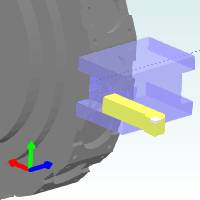
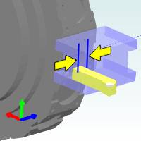
Tip: The station
or substation coordinate system is indicated by a thin-lined gnomon and
the adapter coordinate system is indicated by the thicker gnomon. You
can use the Shift values to temporarily move the adapter away from the
station and make it easier to view both coordinate systems while modifying
the adapter alignment.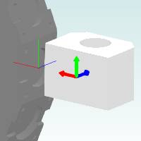
-
Click the down arrow next to Align Adapter X, and select the appropriate axis direction (X, -X, Y, -Y, Z, -Z, or User Defined) of the substation coordinate system to which you want to align the X-axis of the adapter coordinate system.
-
Click the down arrow next to Align Adapter Z, and select the appropriate axis direction (X, -X, Y, -Y, Z, -Z, or User Defined) of the substation coordinate system to which you want to align the Z-axis of the adapter coordinate system.
Note that the Align Adapter Z list is dynamically updated based on the selected Align Adapter X parameter (and vice versa) to include only the appropriate directions based on the previous selection.
When using the User Defined option, the X, Y, and Z boxes become available for you to type values to define a custom direction vector to which the adapter coordinate system (axis) is aligned.
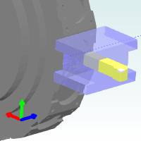
Moving Tools or Adapters Linearly with the Shift Values
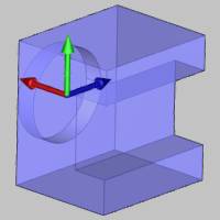
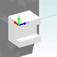
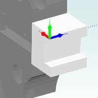
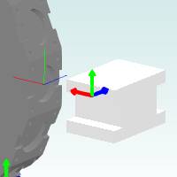
The Shift parameters allow you to move tools or adapters linearly in reference to the mounting location's coordinate system.
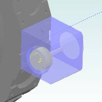
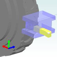
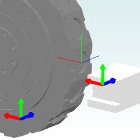
Tip: You can use the dynamic gnomon that displays in the lower-left corner of the preview window as the reference to which way the Shift values move tools or adapters from the mounting location. This gnomon indicates the positive axes directions of the mounting location's coordinate system (when a tool or adapter is selected in the device tree).
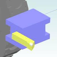
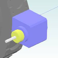
|
Adapter Example |
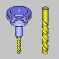
Tool Example |
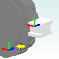
|
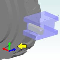
|
These images show the initial mounting of an adapter and tool that are used to illustrate the Shift parameters as follows.
-
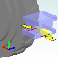
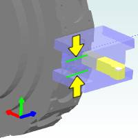
Under Shift, type a positive or negative value in the X box to move the tool or adapter along the X-axis of the mounting location's coordinate system.
Adapter Example
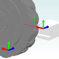
Tool Example
-
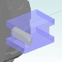
Type a positive or negative value in the Y box to move the tool or adapter along the Y-axis of the mounting location's coordinate system.
Adapter Example
Tool Example
-
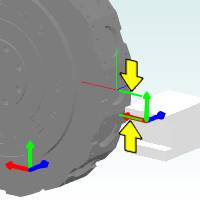
Type a positive or negative value in the Z box to move the tool or adapter along the Z-axis of the mounting location's coordinate system.
Adapter Example
Tool Example
Note that the shifting of the tool and adapter as shown in this example is done for illustrative purposes and may or may not represent realistic shifting.
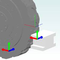
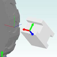
Rotating an Adapter
You can rotate the orientation of an adapter in reference to the substation coordinate system along any of the three coordinate axes: X, Y, or Z.
Tip: You
can use the dynamic gnomon that displays in the lower-left corner of the
preview window as the reference for the Rotation parameters (Angle and
Axis). These two parameters work together to rotate the adapter about
the station or substation mounting location. This gnomon indicates the
positive axes directions of the station's coordinate system (when an adapter
is selected in the device tree).
-
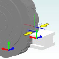
Under Rotation, click the Axis down arrow to select the axis around which you want to rotate the adapter, X, Y, or Z.
Note that you are selecting an axis of the substation coordinate system (not the adapter). -
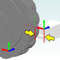
Type a positive or negative value in the Angle box to determine the amount of rotation around the substation coordinate system.
The following images show an adapter that is rotated 45 degrees around the X-axis of the substation (these settings are used for illustrative purposes). Note that the adapter is shifted away from the substation in order to better show the coordinate systems used to rotate the adapter.
Rotating Tools
You can use the Rotation Angle parameters to rotate mill or lathe tools around the Y-axis of the mounting location's coordinate system.
-
Select a tool in the device tree to make its mounting parameters available.
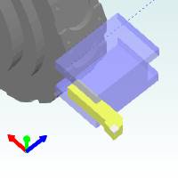
-
Under Rotation, type a positive or negative value in the Angle box, and press Tab to update the preview.
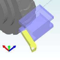
The rotation angle for tools is always around the Y-axis of the mounting location's coordinate system.
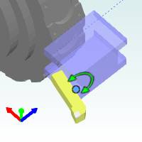
This information explained here can be applied to rotating both mill and lathe tools.