 Probe
Probe
Introduction
This topic explains the options found in the Operation(s) > Probe page of the Probing dialog, and provides links to related topics.
The Probe
From this tool page, you can either, choose a different tool from the Tool Crib, go into the Tool Crib to add tools from your Tool Library, or enter tool specific data manually into the Tool Data Section of the page. This page will also assist in assigning Tool Numbers and Offsets, as well as Speeds and Feeds.
Tip: It is good practice to have all the tools for the job loaded into the Tool Crib at the start of the job. If you do, the tools for the job will already be in the Tool Crib, and the system will have pulled appropriate tools for each operation from the Tool Crib.
- Tool Crib - opens the Tool Crib for you to select a tool
that you have already loaded for the job. Click to select a tool in the
tools list, and click OK to assign the tool to the operation. (For Mill
Turn jobs, view Mill Turn Tool Crib.
- Assign/Edit Tool Holder - Assign Tool Holder opens the Milling Tool Holder Library to assign a tool holder to the tool. In the Tool Holder list on the right, select a tool holder/arbor, then click OK. The name of the selected tool holder appears in the Holder Label box. This holder is now the default tool holder for the tool, meaning that it is automatically assigned to the tool when you create an operation with this tool. Edit Tool Holder opens the Tool Holder Definition dialog.
Tool Data
To select a tool for the feature you can use the following option in one of two ways.
- System
Tool
 Select this check
box to allow the software to automatically select tools from the Tool
Crib that match the machining
operation. In the case of end mills, you may alter the diameter and corner
radius allowing the software to find the appropriate tool from the Tool
Crib. In the case the appropriate tool sizes are not found, the software
searches for a matching tool in the Tool Library. If a matching tool is
found, it is added to the Tool Crib. If a matching tool is not found,
a new tool is automatically created and added to the Tool Crib.
Select this check
box to allow the software to automatically select tools from the Tool
Crib that match the machining
operation. In the case of end mills, you may alter the diameter and corner
radius allowing the software to find the appropriate tool from the Tool
Crib. In the case the appropriate tool sizes are not found, the software
searches for a matching tool in the Tool Library. If a matching tool is
found, it is added to the Tool Crib. If a matching tool is not found,
a new tool is automatically created and added to the Tool Crib. When this check
box is cleared, you can edit all tool information directly in the dialog
box. In this case, the defined tool is added to the Tool Crib
When this check
box is cleared, you can edit all tool information directly in the dialog
box. In this case, the defined tool is added to the Tool Crib - Ball Diameter (1) -
defines the width of the stylus tip.

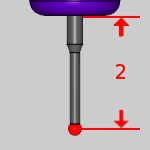
- Length (2) -
defines the distance the stylus protrudes from the main body.
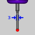
- Stem Diameter (3) - defines the width of the stylus .
- Tool Label - allows you to set, or modify, a tool name.
- Holder
Label - displays the name of the associated tool holder.
When blank, no tool holder is associated.
Machining Data
- Tool Number - opens the Assigned
Tools dialog box for you to change the tool numbering.
- Override Offsets
Clear the Override Offsets check box to use the tool number to set the
Offset Register value.
Select the Override Offsets check box to allow for manual editing of the
Offset Register value. - Height Offset - sets
the Height Offset to be used in the posted program.
- Diameter Offset -
sets the Diameter Offset to used in the posted program.
Feed
- Protected Feedrate - sets the speed at which the probe will move in protected positioning mode. In this mode the probe will stop if it comes in contact with an obstacle.