Assigning Lathe Tool Holders
Introduction
BobCAM allows you to assign geometry to define lathe tool holders that are used with the collision detection options in the Lathe Wizards.
To Assign a Custom Tool Holder
-
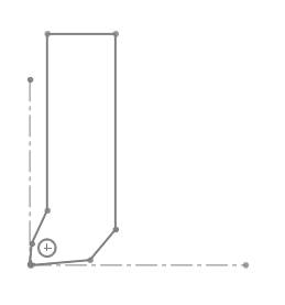
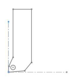
In the graphics area, draw the 2D shape of the holder.
At the position of the attachment point of
the tool insert, place a
Define the X-axis and Y-axis.
-
To open the Tool Library, do one of the following:
-
-
Right-click
 CAM Defaults, and click
Tool Library.
CAM Defaults, and click
Tool Library.
-
-
-
Right-click
 Turning
Tools, and click Tools.
Turning
Tools, and click Tools.
-
-
In the Tool Library, select the lathe tool category that you want to modify.
-
In the list on the right side of the dialog box, click the tool that you want to modify, expand the Tool Parameters on the right side of the dialog.
(If you are creating a new tool, just select the category, and click Add.) -
In the Tool Parameters section, click Edit Tool Holder.
-
In the Tool Holder Definition dialog box, select the radio button for Custom.
-
Click Pick Geometry.
The Tool Holder Definition dialog box hides and the Select Insert/Holder Geometry dialog displays to allow you to select geometry from the graphics area.
-
Click to select the outer geometry of the holder.
The selections display in the Selected Tool Insert/Holder Items box.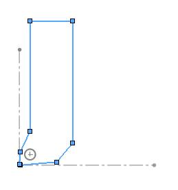
-
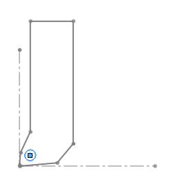
Click the Selected Tool Attachment Circle box, then click the corresponding sketch entity.
-
Click the X-Axis for Insert Geometry box, then click the corresponding sketch entity.
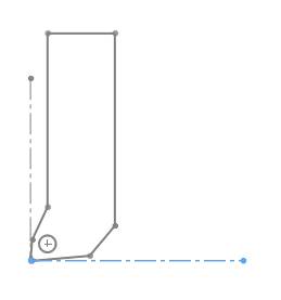
-
Click the Y-Axis for Insert Geometry box, then click the corresponding sketch entity.
-
To finish assigning the tool holder, click
 OK.
OK.
After defining (or updating) all parameters in the tool dialog box, click OK to save the new or modified tool information with the tool holder.