The Tool Holder Definition Dialog
Introduction
The Tool Holder Definition dialog box is used to create tool holders and arbors. This is accomplished by adding and modifying cone and cylinder elements in order to create a accurate representation of the tool holders and arbors.
Important: When using the Tool Holder Definition dialog box, any changes that are made affect the currently selected item. Be sure that you have the proper item selected before changing any values.
| The Tool Holder Parts | |
|
Tool Holder (1)
Tool Arbor (2)
|

|
Navigation
To access the Tool Holder Definition dialog box:
- In the Milling Tool Holder Library dialog box, click AddArbor, EditArbor, Add Holder, or Edit Holder.
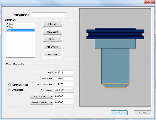
The Tool Holder Definition Parameters
![]() View the
Tool Holder Definition dialog box
View the
Tool Holder Definition dialog box
-
Holder/Arbor Description - is the name of the holder or arbor (depending on what you are creating) in the Milling Tool Holder Library.
Element List
The Element List displays the cone and cylinder elements that are used to create the holder/arbor from the top to the bottom. Select an item from this list to modify. When an element is selected, its parameters are displayed in the Element Parameters group below. The following options are used with the Element List:
- Move
Up - moves the selected element up one level.
- Move
Down - moves the selected element down one level.
- Delete
- removes the selected element.
- Add
Cylinder - adds a cylinder element.
- Add
Cone - adds a cone element.
Element Parameters
The Element Parameters vary depending on the shape chosen.
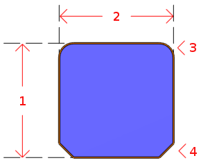
|
Cylinder
|
|
|
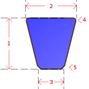
Cone
|
|
Example
The following image shows a cone with the bottom diameter set to 45 degrees. Be aware that the Height and Top Diameter values control the range of possible angles that can be used for Angle Mode.

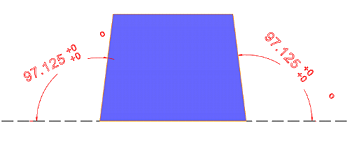
The following image shows a cone with the bottom diameter set to 97.125 degrees.