Geometry Selection Methods
Introduction
There are various methods that can be used when selecting geometry to assign to a machining feature. Being aware of the available selection methods can help you to become more efficient when selecting geometry. This help topic explains the basic selection methods that can be used with the Selection Manager. The available options of the Selection Manager are also explained based on the type of feature that is created.
Selection Methods
There are many ways to select geometry for CAM features. You can select sketch geometry, solid edges, solid faces or surfaces, or you can use the Feature Manager Design Tree to select the CAD feature directly from the tree. Some example images are shown next for different types of features. The Select Whole Bodies option can be used to select entire models with a single click. This allows the software to extract all possible features and add them to the CAM wizard.
Mill Example
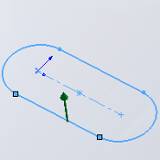
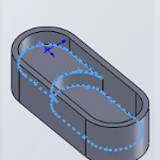
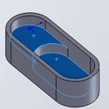
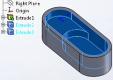
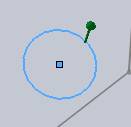
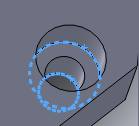
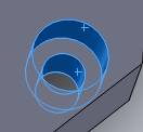
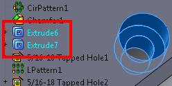
The following images show four different selection methods that can be used to create the same feature.
|
Sketches |
Edges |
Faces |
Features |
|
|
|
|
|
Counter Bore Hole Example
The following images show four different selection methods that can be used to create the same feature. Notice that when selecting edges, the bottom edge is selected, not the top. This is necessary to allow the software to automatically set the proper depths for you.
|
Sketches |
Edges |
Faces |
Features |
|
|
|
|
|
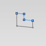
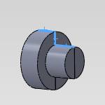
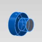
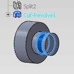
Lathe Example
|
Sketches |
Edges |
Faces |
Features |
|
|
|
|
|
Select Whole Bodies
In addition to the previous selection methods, the Select Whole Bodies check box allows you to select entire models with a single click. BobCAM for SolidWorks then extracts all possible features from the model based on the feature type. When more than one feature is detected, they are added to the tree in the CAM wizard. For many parts and features this works very well, but may create more features than desired. You can simply delete the extra features from the CAM tree after finishing the wizard.
Important Notes About Geometry Selection
Important: You cannot select surface edges and faces together for a single machining feature. You must select either surfaces edges or faces. When using sketch entities and surface edges, you must use one or the other, but not both.
- When selecting sketch entities, for example selecting an arc for a drill hole, only the diameter is automatically set. You must manually set the depth value.
- When selecting surface edges for features, you must select the bottom surface edge to allow the system to automatically set the depth. If you select the top surface edge, then you must manually enter the depth value.
- Although you can select geometry directly from a part model, it can be more efficient to use the Feature Manager design tree to select CAD features.
- When selecting geometry, to clear a selection, you can click an item a second time.
Open Pocketing
When creating open pocketing from solids, the software automatically detects the open pocket (for features that support open pocketing). In some situations you may need to use sketches. When creating open pocketing using sketches, define the open portion of the pocket by changing that part of the sketch to construction geometry. (When using this method, you must select only sketch geometry for the feature, meaning don't mix the selection of sketches and solid edges.)
Important: When selecting sketches for open pocketing, you must select the entities directly from the graphics area. If you select sketch features from the Feature Manager design tree, the construction geometry is filtered out, causing the feature to be recognized as a closed pocket.
The Selection Manager
When you select geometry for a machining feature, the Selection Manager displays in the SolidWorks Property Manager area. All of the Selection Manager options are explained next.
-
 (OK) - confirms the current settings
and geometry selections and closes the Selection Manager.
(OK) - confirms the current settings
and geometry selections and closes the Selection Manager. -
 (Cancel) - closes the Selection
Manager.
(Cancel) - closes the Selection
Manager.
Selection Options
-
Select Whole Bodies
![]() Select the check box to enable whole
body selection. When you click a part model, the entire model is selected.
Single entity selection is disabled. The system automatically creates
multiple features, when necessary, using the selected geometry and Feature
Refinement options seen below.
Select the check box to enable whole
body selection. When you click a part model, the entire model is selected.
Single entity selection is disabled. The system automatically creates
multiple features, when necessary, using the selected geometry and Feature
Refinement options seen below.
![]() Clear the check box to use standard
single entity picking. This allows you to select single sketches, edges,
surfaces, or CAD features.
Clear the check box to use standard
single entity picking. This allows you to select single sketches, edges,
surfaces, or CAD features.
Selected Items
When the Select Whole Bodies check box is cleared, you can select individual sketches, edges, faces, and CAD features from the Feature Manager Design Tree. Each item that you select displays in this box. You can right-click an item in the selected items box to display a shortcut menu with the following options. You can use the Shift and Ctrl modifier keys to select multiple items in the Selected Items or Geometry lists.
-
Clear Selections - removes all of the items in the list.
-
Delete - removes the selected item from the list.
Multiaxis Drive Surface Selection
As you select drive surfaces for multiaxis features, the surface normal direction displays for each face or surface. You use the following options to control the surface normal direction.
-
Display Normals
![]() Select the check box to display the surface normal direction, on entities
that are selected, in the graphics area.
Select the check box to display the surface normal direction, on entities
that are selected, in the graphics area.
![]() Clear the check box to turn off the display of surface normals in the
graphics area.
Clear the check box to turn off the display of surface normals in the
graphics area.
-
Reverse All - reverses the surface normal direction of all the selected entities.
-
Reverse Normal - reverses the surface normal direction of only the entities that are currently selected in the Selected Items box.

Parameters
The following parameters are available for some milling features.
-
Auto Group
![]() Select the check box to allow the software
to automatically group similar machining operations together in order
to minimize the amount of features based on the selected geometry. For
example, when selecting multiple arcs for drilling features, this option
places all of the same diameter holes into one feature.
Select the check box to allow the software
to automatically group similar machining operations together in order
to minimize the amount of features based on the selected geometry. For
example, when selecting multiple arcs for drilling features, this option
places all of the same diameter holes into one feature.
![]() Clear the check box to force the software
to create separate machining features of the same type for each selected
shape.
Clear the check box to force the software
to create separate machining features of the same type for each selected
shape.
- Rapid Plane - sets the rapid height for the feature as an incremental value from the Top of Feature. This defines the default value used in the CAM Wizard.
- Tolerance - is a selection tolerance that is used in the feature detection based on the type of selections made. For most scenarios, you should not have to change this value.
Lathe Parameters
The following parameters are available for Turning features. When using solids for turning features, the software must analyze the model to get the outer or inner profiles needed to properly create turning features. The following parameters allow you to control how the software analyzes the part. For many parts (symmetrical or prismatic shapes) a single section plane is all that is needed. More complicated parts may require more than one section plane, while even trickier parts may require the use of the Spun Profile. When using the Section Planes, you can either type an angle interval or pick locations to automatically set the section angles using the following settings.
Feature Extraction Method
![]() Section Planes
Section Planes
-
Display Section Planes - shows the section planes location on the part as a preview in the graphics area.
Enter Section Angles
The following parameters display when Enter Section Planes is selected.
-
Start Angle - is the reference angle to which BobCAM begins analyzing the profile of the feature geometry. The zero degree location is the XZ plane (by default).
-
Interval Angle - a new section plane is created at this interval for determining the number of section planes used to analyze the part geometry.
-
The Section Angles box displays all angles at which a section plane is created. You can click the angles listed in this box to highlight the section plane in the graphics area (Display Section Planes must selected.)
Pick Section Angles
When this option is selected, you can set the section planes by selecting points or vertices in the graphics area. The entities that you select display in the box under Pick Section Angles. To access a shortcut menu for removing selections, right-click inside the box.
-
The Section Angles box displays all angles at which a section plane is created. You can click the angles listed in this box to highlight the section plane in the graphics area. (Display Section Planes must selected.) This also automatically selects the entity in the Selected Items list.
![]() Spun Profile
Spun Profile
 Arc Fit - creates arcs where possible based
on the tolerance selected. Clearing this check box will produces
lines only.
Arc Fit - creates arcs where possible based
on the tolerance selected. Clearing this check box will produces
lines only.
The following options display when selecting geometry for most turning features. These options are not needed when selecting geometry for a groove feature.
Feature Refinement
-
Remove first vertical
line - removes the first vertical
line (front face) from the detected feature geometry.
-
Remove last vertical
line - removes the last vertical
line (back face) from the detected feature geometry.
Options
The Options section of the Selection Manager contains different parameters depending on the type of machining feature. The options are most often applied to Drill Hole and 2 Axis features as explained next.
Drill Features (Drill Hole only)
-
Minimum Hole Diameter - is the smallest hole diameter that is used for the current drilling feature.
-
Maximum Hole Diameter - is the largest hole diameter is used for the current drilling feature.
2 Axis Features
-
Gouge Check
![]() Select the check box to allow the system to gouge check the feature. The
Horizontal Extension check box becomes available.
Select the check box to allow the system to gouge check the feature. The
Horizontal Extension check box becomes available.
![]() Clear the check box to turn off the gouge checking option.
Clear the check box to turn off the gouge checking option.
-
Horizontal Extension
![]() Select the check box to allow the software
to make adjustments to the boundaries of the selected geometry to provide
a more optimal toolpath. For example, when creating pockets of multiple
depths. This can be used to extend a selected surface to the boundaries
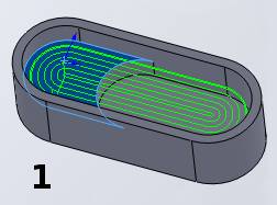
of the part and have the feature cut the entire area to the same depth.
This is shown in the following example.
Select the check box to allow the software
to make adjustments to the boundaries of the selected geometry to provide
a more optimal toolpath. For example, when creating pockets of multiple
depths. This can be used to extend a selected surface to the boundaries
of the part and have the feature cut the entire area to the same depth.
This is shown in the following example.
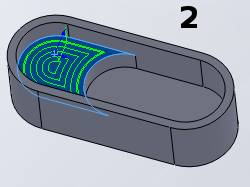
![]() Clear the check box to create the feature based on the selected geometry
only.
Clear the check box to create the feature based on the selected geometry
only.
|
|
|
|
|
Hole Drilling Selection Manager
View the Hole Geometry Selection Manager to learn about all Selection Manager options when selecting geometry for drilling features.
BobART - Selecting Emboss (Art) Models
To learn about selecting emboss models for CAM features, view Selecting Art (Emboss) Models.
Geometry Selection Example
Loop Selection
The following example shows you how to use the SolidWorks loop selection options.
-
In this example you want to profile the outside of this part. When selecting the geometry for the feature, point to the bottom edge of the part and right-click to display a shortcut menu.
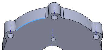
-
Click Select Loop to automatically select a loop connected to that edge. Notice that the vertical face was selected. To change the selection to the bottom loop, click the yellow arrow shown next.
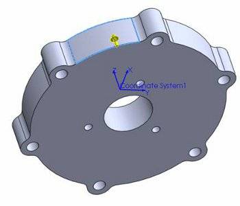
-
By clicking the selection arrow one time, the selection changes to the desired bottom loop. Now click
in the Selection Manager and you are ready to edit the machining feature
in the CAM tree.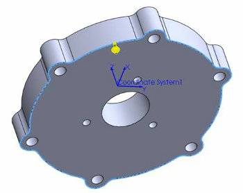
-
Suppose that you do not want to select the entire profile, point to the edge, right-click and click Select Partial Loop. This allows you to manually click edges and list them in the Selection Manager. When finished, click
OK.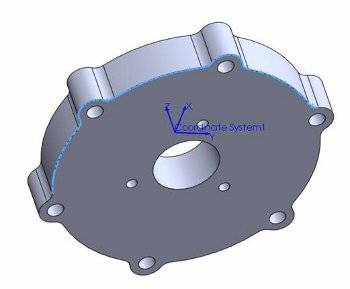
The next image shows the Profile feature used with partial loop selected.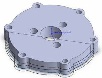
If you need to clear the selections or delete an item, right-click an item in the Selected Items list and select the appropriate command. You can also click a selection in the graphics area to clear the selection.