Machine Compensation
Introduction
This example will demonstrate using machine compensation in CAM operations, and will provide links to related topics.
System and Machine Compensation Example
For each operation you can choose to use compensation or not. When using compensation, you can choose to use System Compensation, Machine Compensation, or a combination of both. This example will explore machine compensation and the direction of the selected chain.
Important: When using machine compensation, the offset depends entirely on the value entered for the tool in the controller.
Create a Mill 2 Axis Feature
- In the CAM Tree, right-click the Machine Setup - 1 and select Mill 2 Axis.
The Mill 2 Axis Wizard appears.
Feature Geometry Picking
- Click Select Geometry.
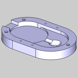
The Feature Geometry Picking dialog appears. Focus is automatically placed on the Selected Geometry list allowing you to choose the feature geometry from the graphics area.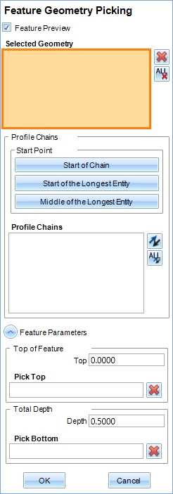
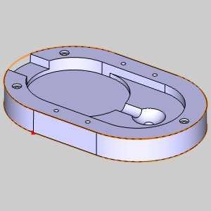
- In the graphics area,

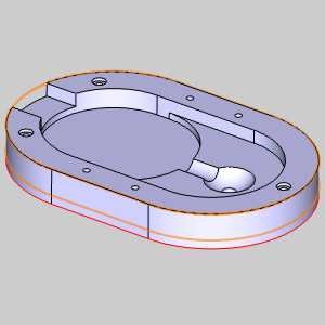
The geometry is added to the Selected Geometry list, and the feature preview is visible.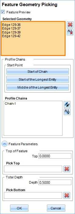
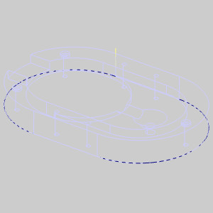
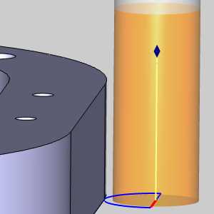
- In the Profile Chains list of the Feature Geometry Picking dialog, click Chain-1.
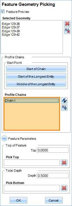
The chain direction is displayed in the graphics area.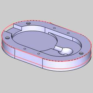
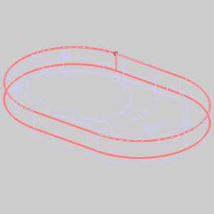
We will leave our chain in its counter clockwise direction for now. - At the bottom of the Feature Geometry Picking dialog, click in the Pick Bottom list.
The list is given focus.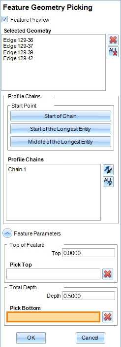
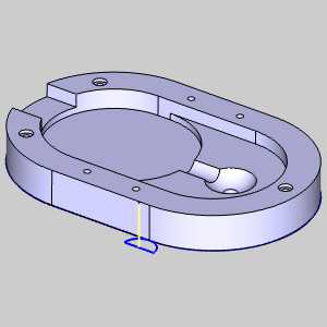
- In the graphics area, click the bottom edge of the model.
The snap point is added to the Pick Bottom list, and the Depth is updated.
Note: Clicking the actual snap point that appears is not necessary. When you select an edge to pick a point, the closest snap point is always used.
- Click OK.
The Mill 2 Axis Wizard reappears.
Setting the Machining Strategy
- In the tree in the left of the wizard, click Machining Strategy.
- In the Current Operations list, highlight Profile Rough and click the Delete button.
Setting Compensation
- In the tree in the left of the wizard, click Patterns.
- In the Compensation group, set the System Compensation to Off.
- In the Compensation group, set the Machine Compensation to Comp Right / G42.
Setting Leads
- In the tree in the left of the wizard, click Leads.
- In the Lead-in group, select Circular.
- In the Line group, set the Length to 0.0000.
- In the Arc group, set the Radius to 0.2000.
- Click Compute.
The toolpath is created.
Warning: When using machine compensation, be sure to use a lead-in and a lead-out. Machine compensation is only called during a linear lead-in motion, and canceled during a linear lead-out. Because of this, it is also important to make sure the lead is large enough to accommodate the tool radius having no compensation at the start, and only fully compensated at the end of the first linear lead move. Since we are using the default tool with a quarter inch radius, this is why we set the radius on our Arc Leads to 0.3000.
Testing the Output Code
- In the CAM Tree, right-click Milling Job, and select Post.
The posted code appears in the Post Manager.
Notice there is no G42 output in the code. This is because we are not using a lead with a linear move.
Updating the Leads
- In the CAM Tree, right-click Feature 2 Axis, and select Edit.
The Mill 2 Axis Wizard appears. - In the tree in the left of the wizard, click Leads.
- In the Lead-in group, select Circular.
- In the Line group, set the Length to 0.0000.
- In the Arc group, set the Radius to 0.2000.
- Click Compute.
The toolpath is created.
Testing the Output Code
- In the CAM Tree, right-click Milling Job, and select Post.
The posted code appears in the Post Manager.
Notice there is no G42 output in the code. Again, this is because we are not using a lead with a linear move.
Updating the Leads
- In the CAM Tree, right-click Feature 2 Axis, and select Edit.
The Mill 2 Axis Wizard appears. - In the tree in the left of the wizard, click Leads.
- In the Line group, set the Length to 0.2000.
- Click Compute.
The toolpath is created.
Testing the Output Code
- In the CAM Tree, right-click Milling Job, and select Post.
The posted code appears in the Post Manager.
Notice we are now outputting our G42 in the code. Also notice how the compensation code is called after the tool is at depth, and prior to the first linear move. This means that it will only be properly compensated at the end of our first linear move. We will want to test this to make sure our first position, prior to compensation is not an issue.
Testing the Initial Position
- Since our toolpath is showing the tool position with no compensation, we can backplot the first position to make sure we are avoiding a gouge.
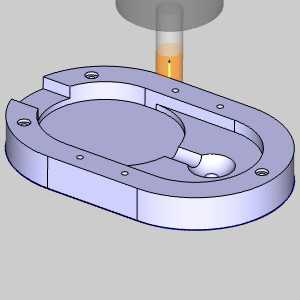
In the CAM Tree, under Feature 2 Axis, right-click Profile Finish, and select Backplot.
The Backplot dialog appears. - Click Next twice to move the tool to the Feed Plane, and then to our Total Depth, and zoom in to the tool.

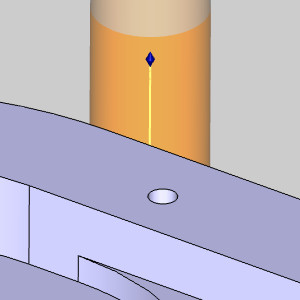
Notice how the tool is biting into the part. This is because we are using a 0.5000 inch diameter tool, and a 0.2000 inch lead. - In the Backplot dialog, click Close.
The Backplot dialog closes.
Updating the Leads
- In the CAM Tree, right-click Feature 2 Axis, and select Edit.
The Mill 2 Axis Wizard appears. - In the tree in the left of the wizard, click Leads.
- In the Line group, set the Length to 0.3000.
- In the Arc group, set the Radius to 0.3000.
- Click Compute.
The toolpath is created.
Testing the Initial Position
- In the CAM Tree, under Feature 2 Axis, right-click Profile Finish, and select Backplot.
The Backplot dialog appears. - Click Next twice to move the tool to the Feed Plane, and then to our Total Depth, and zoom in to the tool.
- Rotate the view to verify the tool position.
Notice how the tool is set away from the part. This is because we are using a 0.5000 inch diameter tool, and a 0.3000 inch lead. - In the Backplot dialog, click Close.
The Backplot dialog closes.
With the counter clockwise direction of our chain, and compensation to the right, we are currently using a conventional cut.
We will change this to a climb cut.
Updating the Compensation
- In the CAM Tree, right-click Feature 2 Axis and select Edit.
The Mill 2 Axis Wizard returns. - In the tree on the left side of the wizard, click Patterns to open the Patterns page.
- In the Compensation group, change Machine Compensation to Comp Left / G41.
- Click Finish.
Updating the Chain direction
- In the CAM Tree, right-click the Geometry item in our Feature 2 Axis, and select Re/Select.
The Feature Geometry Picking dialog opens. - In the Profile Chains list, click Chain-1.
The chain is displayed in the graphics area. - Click the closer side of the part.


The chain start point moves to the closes snap point.
Our direction is still counter clockwise. - Click the same area.
The chain reverses direction. - Click OK.
The Feature Geometry Picking dialog closes. - In the CAM Tree, right-click Feature 2 Axis and select Compute All Toolpath.
The toolpath is updated, and we are now using a climb cut.