How it Works: Clearance Angle
Introduction
This topic explains the Clearance angle option found in the Parameters dialog.
Navigation
- In the Strategy and parameters group of the Gouge check page, click the first drop down list, and select Tilt tool.
With this option selected, select Use lead/lag angle, or Use side tilt angle from the second drop down list, then click the Parameters button found below.
How it Works
-
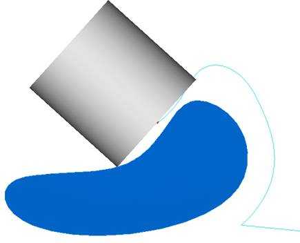
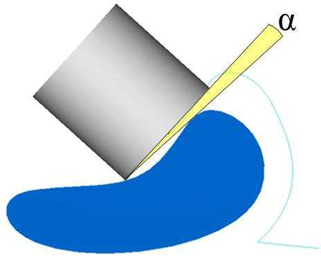
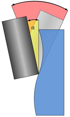
This image shows the Clearance angle (yellow) applied to the side of the tool. The original position of the tool is colliding with the wall. With the clearance angle applied, the tool rotates around the tool contact point, away from the collision point, until the clearance angle is reached. It is important that the clearance angle lies in the range of the Maximum tilt angle (red).
-
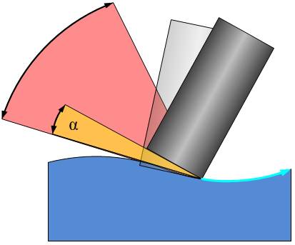
This image shows the Clearance angle applied to the tip of the tool. The original position of the tool is colliding with the floor. With the clearance angle applied, the tool rotates around the tool contact point, away from the collision point, until the clearance angle is reached. It is important that the clearance angle lies in the range of the Maximum tilt angle (red).
Example
-
This example show a machining of a turbine blade shaped geometry. The contact point of the tool is set to the front.
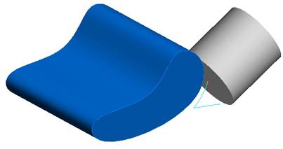
-
During machining, the tool starts colliding with the back side of the flat end.
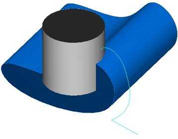
-
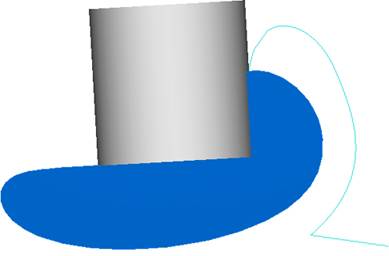
With the gouge check activated, the clearance angle is set to zero degrees. The tool doesn't collide anymore, but it barely touches with the backside.
-
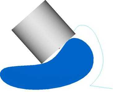
With the clearance angle set to five degrees, the tool is cleared from the collision.
