Emboss Texture Weave Example 1
Introduction
This help topic explains how to create an Emboss Texture Weave feature. In this example, a weave texture is applied to the background of a sign that was created using an Emboss from Component feature.
Example File
The part file for this tutorial is available for download at: http://www.bobcad.com/helpfiles. If you are connected to the Internet, you can click the link provided to download and save the Emboss Texture Weave Example 1.SLDPRT zip file. After downloading the zip file, extract the files on your system in a place that is easy to remember. You can then open the file to use with this tutorial.
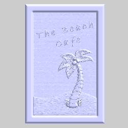
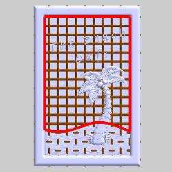
The component (sign) used for this tutorial is shown next. The stock is the same size as the component, which has already been created in the example file.
Part 1) Open the Example File
-
In the File menu, click Open.
-
In the Open dialog box, select the folder in which you extracted the example file.
-
Select Emboss Texture Weave Example 1.SLDPRT, and click Open.
-
In the Manager Pane, click the
 BobART Manager tab.
 -
Next to
 Emboss
Model, click
Emboss
Model, click  to
expand the tree.
to
expand the tree.
Notice that the ![]() Beach Cafe Sign
feature already exists.
Beach Cafe Sign
feature already exists.
Part 2) Add the Feature and Regenerate the Model
-
In the
BobART
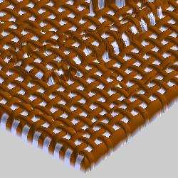
tree, right-click Emboss Model, point to Emboss Texture, and click Weave. -
In the Texture-Weave dialog, in the Emboss Attributes group, click Color.
In the Color dialog box, click any color for the feature, and click OK. (This example uses a brown color.) -
In the Name box, select the text, and type My Weave.
-
To close the dialog box, click OK.
The My Weave feature
is added to the tree.
My Weave feature
is added to the tree. -
In the
BobART
tree, right-click  Emboss Model,
and click Regenerate.
Emboss Model,
and click Regenerate.
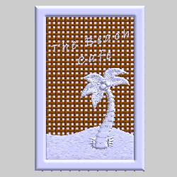
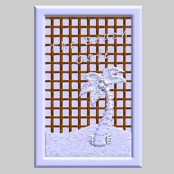
The new feature is added to the embossed model in the graphics area.

When no Boundary Geometry is assigned for the feature, the texture-weave is applied to the entire model. (A boundary is selected later in this example.)
In addition to the fact that no boundary has been defined, the selected Application Type, Add, causes the feature to be added to the existing feature. This is changed in the next part.
Part 3) Edit the Feature and Change the Application Type
-
In the BobART tree, right-click
 My Weave, and click Edit.
 -
In the Texture-Weave dialog box, click the Application Type arrow, and click Merge High.
-
To close the dialog box, click OK.
-
To update the changes on the model, right-click
Emboss Model, and click Regenerate.
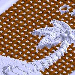
Note: The Merge High application type keeps only the highest portion of the model. Because the total height of the weave is less than the total height of the component, the weave is now only contained in the area of the model that is less than the height of the weave.
Part 4) Edit the Feature Cross Section
In this section, you change the cross-section shape to see how the cross section is applied to the weave. To better view the cross-section shape, we suppress the sign so that only the weave is shown.
-
In the BobART tree, right-click
Beach Cafe Sign, and click
Suppress/Unsuppress. -
Right-click
Emboss
Model, and click Regenerate.
Now only the weave is visible.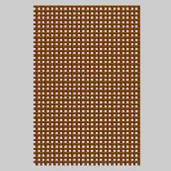
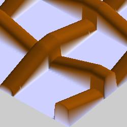
When the view is rotated, the cross-section shape is easier to view. The following images compare the cross section defined in the Texture-Weave dialog box to the result on the model.

-
In the BobART tree, right-click
My Weave, and click Edit. -
In the Cross-Section Shape group, click the Shape Style arrow, and click Concave Arc.
-
To close the dialog box, click OK.
-
Right-click
Emboss
Model, and click Regenerate.

The following images compare the cross section defined in the Texture-Weave dialog box to the result on the model.


About the Cross-Section
Shape Total Width:
The Total Width parameter in the Texture-Weave
dialog box defines the width of each row/column of the weave. Generally,
in order to create predictable results, the Total Width should be at least
twice the width of the cross section (for example, the Radius or Major
Axis). The following examples both use a cross-section Radius of 0.100.
The Total Width of 0.250 allows the cross-section shape to be fully defined
across each row/column of the weave. The Total Width of 0.125 does not
create the same result. A portion of the cross-section shape is removed
to fit the defined Total Width. (The Drive Curve-Peak Length parameter,
explained in Part 5, also affects the result.)
|
Total Width 0.250 |
Total Width 0.125 |

|

|
The previous information is a recommendation
and may not always be followed.
Part 5) Edit the Feature Driving Curve Shape
-
Right-click My Weave, and click Edit.
-
In the Driving Curve Shape group, click to clear the
 Smooth Curve check box.
This makes the weave appear as the straight-line Driving Curve Shape that displays in the Texture-Weave dialog box.
In the Cross-Section Shape group, click the Shape Style arrow, and click Convex Arc.
To close the dialog box, click OK. -
Right-click
Emboss
Model, and click Regenerate.
-
Right-click My Weave, and click Edit.
In the Driving Curve Shape group, change the Length to 1.000, and change the ZHeight to 0.250.
Click OK to close the dialog box. -
Right-click
Emboss
Model, and click Regenerate.
The previous settings make it easier to see the result of the defined drive curve parameters, Length (1) and Z Height (2), as shown next.

When the Peak Length (3) is changed to 0.500, the result is as follows.

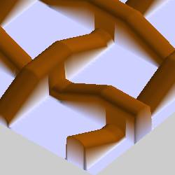
Tip: The Peak Length shown in the previous steps was increased from 0.250 to 0.500. This means that the Total Width of the Cross Section Shape can now also be increased up to 0.500 (and still create predictable results). Again, this is a recommendation that may not always be followed. (For example, you may want to set the Total Width greater than the Peak Length if it creates desired results.)
Part 6) Assign Boundary Geometry
-
In the BobART tree, right-click Beach Cafe Sign, and click Suppress/Unsuppress.
-
Right-click
Emboss
Model, and click Regenerate.

The currently defined parameters cause the texture to appear in an area of the model that is not desired. To contain a texture, you assign a boundary. -
Under My Weave, right-click
 Boundary Geometry, and click
Re/Select.
Boundary Geometry, and click
Re/Select.
In the Feature Manager design tree, select the Inside Boundary feature.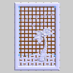
To confirm the selection, click .
.
-
To update the model, right-click
Embossed
Model, and click Regenerate.
The texture is now contained within the selected boundary.

Part 7) Edit the Feature and Create a Solid Texture
For the final part of this example, the weave is edited to form a solid background texture for the sign.
-
Right-click My Weave, and click Edit.
-
In the Driving Curve Shape group:
Set the Length to 0.500.
Set the Z Height to 0.100.
Set the Peak Length to 0.250.
Click to select the Smooth Curve check box.
 -
In the Cross-Section Shape group:
Set the Total Width to 0.500.
Click the Shape Style arrow, and click Line.
Set the Height to 0.100, and set the Slope Angle to 90.00.
Click OK to close the dialog box. -
Regenerate the model.

Because the Cross-Section Shape-Total Width parameter is the same value as the Driving Curve Shape-Length parameter, the weave no longer contains any space between each row/column.
Part 8) Change the Rotation Angle
When you Edit the feature and change the Rotation Angle to 22.00, the regenerated result is as follows. (The rotation angle is measured from the X-axis.)


This concludes the tutorial.