Pig Art Emboss Tutorial
Introduction
This tutorial is designed to help you become familiar with the BobART Emboss features. The Emboss Regular, Emboss Swept, and Emboss 2-Rail Sweep features are used to create a piggy-bank BobART model. Follow this tutorial along with the other Emboss tutorials to learn more about the BobART Emboss features.
Example File
The part file for this tutorial is available for download at: http://www.bobcad.com/helpfiles. If you are connected to the Internet, you can click the link provided to download and save the Pig Art Emboss Example.sldprt zip file. After downloading the zip file, extract the files on your system in a place that is easy to remember. You can then open the file (.sldprt) to use with this tutorial.
Part 1) Open the Example File
-
in the File menu, click Open.
The Open dialog box is displayed. -
Select the folder in which you saved the example file.
-
Select Pig Art Emboss.sldprt, and click Open.
The file is opened and the geometry is displayed
in the graphics area.
Part 2) Regular Emboss 1 - Body
Insert the Feature and Define Stock
-
In the
 BobART Manager tab, right-click
  Emboss
Model, and click Emboss Regular.
Emboss
Model, and click Emboss Regular.
The Stock Parameters dialog box opens. -
In the Model Size group, set the X value to 9.00, and set the Y value to 12.00.
Note: The resolution updates automatically as the size is updated. The Resolution will improve the quality of the model, but also increase the size of the file, and the amount of time it takes to regenerate the surface.
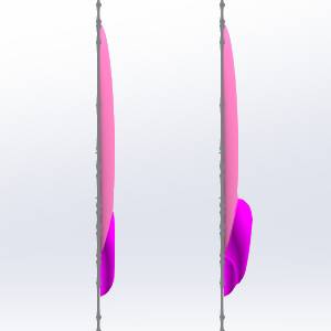
The image on the left shows stock with a resolution of 25, while the image on the right shows stock with a resolution of 150.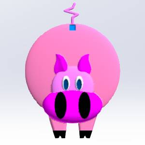
Normally, since ultra fine details will not be visible on the final machined part, a higher resolution stock is not really needed. However, if it is wanted, wait until the model is complete and adjust the resolution at the end. This will keep regeneration times low during the creation of the model.
- Select the Remove Non-Emboss Area check box.
-
Click OK.
The Emboss dialog box opens.
Edit the Feature Parameters
-
In the Emboss Attributes group, change the Name to Body.
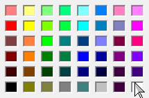
- Click Color.
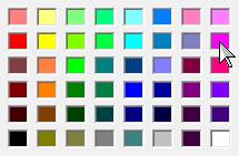
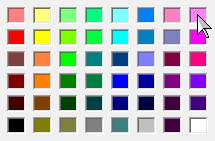
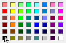
The Color dialog appears.
Select pink.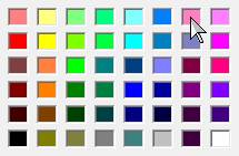
- Click OK.
The Color dialog disappears. -
Click the Cross Section arrow, and click Convex Ellipse.
In the Major Axis box, type 4.00.
In the Minor Axis box, type 0.50. -
Click the Application Type arrow, and click Add.
The Add application type adds the emboss to the stock surface. - Click OK.
Select Feature Geometry
-
Under
 Body - Add, right-click

 Geometry,
and click
Re/Select.
Geometry,
and click
Re/Select. -
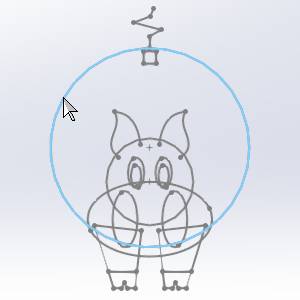
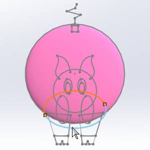
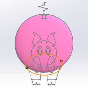
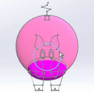
In the graphics area, select the geometry that represents the body of the pig as shown next.

To confirm the selection, click ![]() (OK) in the Property Manager.
(OK) in the Property Manager.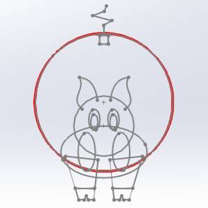
Generate the Emboss
-
Right-click
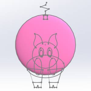
Emboss Model, and click Regenerate.
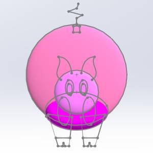
The body is now embossed and appears as shown next.
Part 3) Regular Emboss 2 - Nose
Insert and Edit the Feature
-
Right-click
Emboss
Model, and click Emboss Regular.
The Emboss dialog box opens. -
Change the Name to Nose.
- Click Color,
select pink, and click OK.
-
Under Emboss, click the Cross Section arrow, and click Convex Ellipse.
In the Major Axis box, type 0.750.
In the Minor Axis box, type 0.500. -
Under Application Type, click the arrow, and click Merge High.
Click OK.
Note: Most, but not all of the nose geometry overlaps the body geometry. Merge High is used to create the nose with one consistent height. If the Add application type is used, then the area of the nose that does not overlap the body geometry would not be the same height as the rest of the nose (this is shown at the end of Part 3). Merge High leaves only the highest area of intersection between two embossed features.
Select Feature Geometry
-
Under
Nose - Merge High, right-click Geometry,
and click
Re/Select. -
In the graphics area, select the geometry that represents the nose of the pig as shown next.
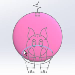
Click ![]() (OK).
(OK).
Tip: To hide
or show the stock, you can right-click ![]() Emboss Model and select Blank/Unblank.
Emboss Model and select Blank/Unblank.
Generate the Emboss
-
Right-click Emboss Model, and click Regenerate.
The nose is now embossed and appears as shown next.

For comparison, an image of the same feature is shown using the Merge High on the left, and Add on the right, as mentioned previously.
Part 4) Regular Emboss 3 - Face
Insert and Edit the Feature
-
Right-click
Emboss
Model, and click Emboss Regular. -
Change the Name to Face.
- Click Color,
select pink, and click OK.
-
Click the Cross Section arrow, and select Convex Ellipse.
In the Major Axis box, type 1.000.
In the Minor Axis box, type 0.250. -
Click the Application Type arrow, and click Merge High.
Click OK.
Select Feature Geometry
-
Under
Face - Merge High, right-click Geometry,
and click
Re/Select. -
In the graphics area, select the geometry that represents the face of the pig as shown next.

Click ![]() OK.
OK.
Generate the Emboss
-
Right-click
Emboss
Model, and click Regenerate.
Notice that the face emboss does not show. This is because the height of the body is greater than the height of the face, and the Merge High application type is used. -
To edit the feature, right-click
 Face - Merge High, and click
Edit.
Face - Merge High, and click
Edit.
In the Base Height box, type 0.500.
This adds a 0.500 inch wall to the base of the emboss feature which can now extend up through the body.
Click OK. -
Right-click Emboss Model, and click Regenerate. The result should look as follows.
-
Notice that the face now covers the nose. This is not the desired result. To resolve this issue you add a base height to the nose emboss operation.
-
Right-click
Nose - Merge High, and click Edit.
In the Base Height box, type 0.375. This adds a 0.375 inch base to the nose feature.
Click OK. -
Right-click
Emboss
Model, and click Regenerate.
The model should appear as follows.

Part 5) Regular Emboss 4 - Nostrils
Insert and Edit the Feature
-
Right-click
Emboss
Model, and click Emboss Regular. -
Change the Name to Nostrils.
- Click Color,
select black, and click OK.
-
Under Cross Section, select Convex ARC.
Confirm the Radius is set to 0.250.
In the Start Angle box, type 60.00.
Confirm the End Angle is set to 90.00.
Tip: Notice
that the Start Angle is changed to 60 degrees, instead of 0 degrees. The
embossed model now starts 60 degrees into the defined Cross Section. The
result is that the edge of the model has a more gradual slope in relation
to the stock. The following image shows two identical Regular Emboss features
with the first starting at 0 degrees, and the second starting at 60 degrees.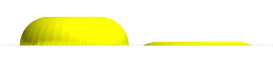
It is important to explore the various settings
of the Emboss features. Changing one setting can create a substantial
difference in the result. By experimenting with the different settings,
you can find multiple ways to accomplish the same task, with variations
in the result. Knowing these variations helps you greatly when creating
embossed models.
-
Click the Application Type arrow, and click Subtract.
The Subtract application type removes material. This makes the nostrils recessed into the nose.
Click OK.
Select Feature Geometry
-
Under
Nostrils - Subtract, right-click Geometry,
and click
Re/Select. -
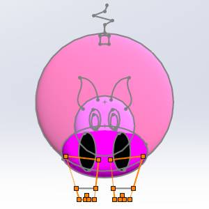
In the graphics area, select the geometry that represents the nostrils of the pig as shown next.
Click ![]() OK.
OK.
Generate the Emboss
-
Right-click
Emboss
Model, and click Regenerate.
The result is shown next.
Part 6) Regular Emboss 5 - Legs
Insert and Edit the Feature
-
Right-click
Emboss
Model, and click Emboss Regular. -
Update the Name to Legs.
- Click Color,
select pink, and click OK.
-
Under Cross Section, select Convex ARC.
Confirm the Radius is set to 0.250.
Confirm the Start Angle is set to 0.00.
Confirm the End Angle is set to 90.00. -
Click the Application Type arrow, and click Merge High.
Click OK.
Select Feature Geometry
-
Under
Legs - Merge High, right-click Geometry,
and click
Re/Select. -
In the graphics area, select the geometry that represents the legs of the pig as shown next.
Click ![]() OK.
OK.
Generate the Emboss
-
Right-click
Emboss
Model, and click Regenerate.
The result is shown next.
Part 7) Regular Emboss 6 - Tootsies
Insert and Edit the Feature
-
Right-click
Emboss
Model, and click Emboss Regular. -
Update the Name to Tootsies.
- Click Color,
select black, and click OK.
-
Under Cross Section, select Convex ARC.
In the Radius box, type to 0.100.
Confirm the Start Angle is set to 0.00.
Confirm the End Angle is set to 90.00. -
Click the Application Type arrow, and click Add.
Click OK.
Select Feature Geometry
-
Under
Tootsies - Add, right-click Geometry,
and click
Re/Select. -
In the graphics area, select the geometry that represents the feet of the pig as shown next.
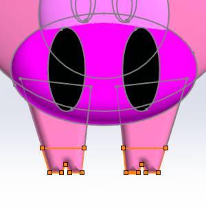
Click ![]() OK.
OK.
Generate the Emboss
-
Right-click
Emboss
Model, and click Regenerate.
The result should look like next image.

Part 8) Regular Emboss 7 - Eyes
Insert and Edit the Feature
-
Right-click
Emboss
Model, and click Emboss Regular. -
Update the Name to Eyes.
- Click Color,
select white, and click OK.
-
Under Cross Section, select Convex ARC.
In the Radius box, type 0.125.
Confirm the Start Angle is set to 0.00.
Confirm the End Angle is set to 90.00. -
Click the Application Type arrow, and click Merge High.
-
In the Base Height box, type 0.75.
Click OK.
Select Feature Geometry
-
Under
Eyes - Merge High, right-click Geometry,
and click
Re/Select. -
In the graphics area, select the geometry that represents the eyes of the pig as shown next.

Click ![]() OK.
OK.
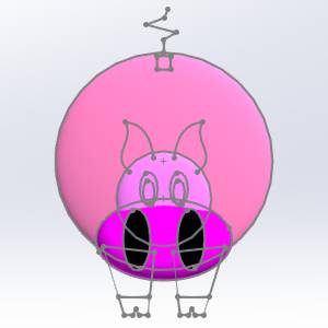
Generate the Emboss
-
Right-click
Emboss
Model, and click Regenerate.
The result is shown next.
Part 9) Regular Emboss 8 - Pupils
Insert and Edit the Feature
-
Right-click
Emboss
Model, and click Emboss Regular. -
Update the Name to Pupils.
- Click Color,
select blue, and click OK.
-
Under Cross Section, select Convex ARC.
In the Radius box, type 0.125.
Confirm the Start Angle is set to 0.00.
Confirm the End Angle is set to 90.00. -
Click the Application Type arrow, and click Subtract.
Click OK.
Select Feature Geometry
-
Under
Pupils - Subtract, right-click Geometry, and click Re/Select. -
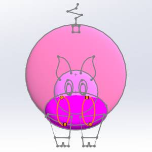
In the graphics area, select the geometry that represents the pupils of the pig as shown next.

Click ![]() OK.
OK.
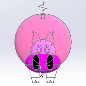
Generate the Emboss
-
Right-click
Emboss
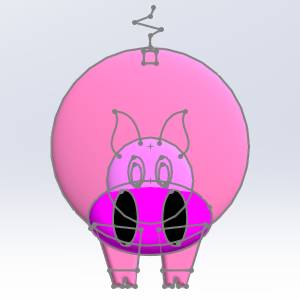
Model, and click Regenerate.
The result should look as follows.

Part 10) Regular Emboss 9 - Coin Slot
Insert and Edit the Feature
-
Right-click
Emboss
Model, and click Emboss Regular. -
Update the Name to Coin Slot.
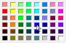
- Click Color,
select blue, and click OK.
-
Under Cross Section, select Convex ARC.
In the Radius box, type 0.125.
Confirm the Start Angle is set to 0.00.
Confirm the End Angle is set to 90.00. -
Click the Application Type arrow, and click Subtract.
Click OK.
Select Feature Geometry
-
Under
Coin Slot - Subtract, right-click Geometry,
and click
Re/Select. -
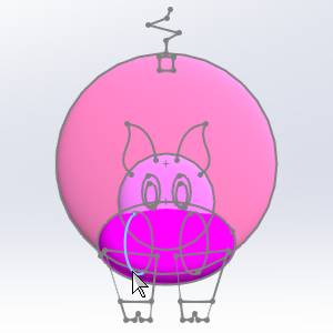
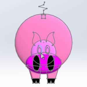
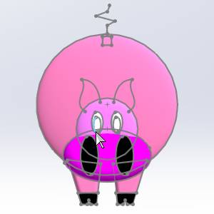
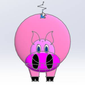
In the graphics area, select the geometry that represents the coin slot of the pig as shown next.


Click ![]() OK.
OK.
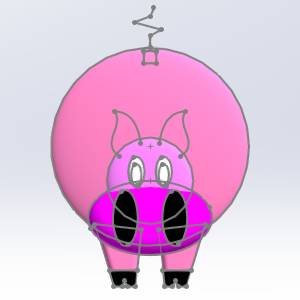
Generate the Emboss
-
Right-click
Emboss
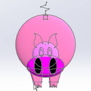
Model, and click Regenerate.
The result should look like the following image.

Part 11) Swept Emboss 10 - Tail
Insert and Edit the Feature
-
Right-click
Emboss
Model, and click Emboss Swept. -
Update the Name to Tail.
- Click Color,
select pink, and click OK.
-
Under Cross Section, select Convex ARC.
In the Radius box, type 0.125.
Confirm the Start Angle is set to 0.00.
Confirm the End Angle is set to 90.00. -
Click the Application Type arrow, and click Merge High.
Click OK.
Select the Geometry
-
Under
Tail - Merge High, right-click Geometry, and click
Re/Select. -
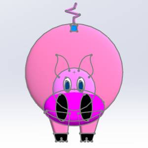
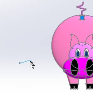
In the graphics area, select the geometry that represents the tail of the pig as shown next.

Click ![]() OK.
OK.
Tip: Notice that the tail geometry is not a closed entity. This is why the Emboss Swept feature is used. The Emboss Swept feature allows the use of open or closed feature geometry, and it creates an emboss using the geometry as the center line for the feature.
At this point, the feature tree is becoming rather
large. You may want to collapse a few of the features to save space in
the BobART Tree. To collapse the features, click the ![]() icon next to each feature name.
icon next to each feature name.
Generate the Emboss
-
Right-click
Emboss
Model, and click Regenerate.
The result is shown next.
Part 12) Emboss 2-Rail Sweep 11 - Right Ear
Insert and Edit the Feature
-
Right-click
Emboss
Model, and click Emboss 2
Rail Sweep. -
Update the Name to Right Ear.
- Click Color,
select pink, and click OK.
-
Click the Application Type arrow, and click Merge High.
-
In the Base Height box, type 0.500.
Click OK.
Select Feature Geometry
-
Under
Right Ear - Merge High, right-click Rail
1-Geometry, and click Re/Select. -
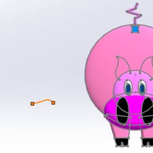
In the graphics area, select the geometry that represents the outer edge of the pig's right ear as follows.

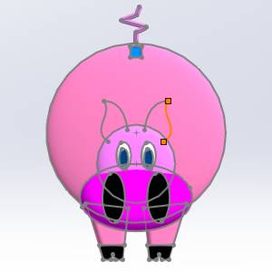
Click ![]() OK.
OK.
The chain direction should point up away from the pig's face.
Tip: To reverse the chain direction, right-click the Rail Geometry (or Cross-Section Geometry) item, and click Reverse Direction.
-
Under
Right Ear - Merge
High, right-click Rail 2-Geometry,
and click
Re/Select.
In the graphics area, select the geometry that represents the inner edge of the pig's right ear as shown in the next image.

Click OK.
OK.
The chain direction should point up away from the pig's face as shown in the previous image on the right. -
Right-click
Cross-Section Geometry-1,
and click Re/Select. -
In the graphics area, to the left of the stock, select the geometry, and click
OK.
Generate the Emboss
-
Right-click
Emboss Model, and click
Regenerate. The model should
appear as follows.

Adjust results
- Under Right Ear - Merge
High, right-click Cross-Section Geometry-1,
and select Reverse Direction.
- Right-click Emboss
Model, and click Regenerate.
The model should appear as shown next.

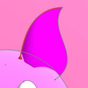
Notice how the cross section is applied to the rails. The start of the cross section is attached to the first rail. - Under Right Ear - Merge
High, right-click Cross-Section Geometry-1,
and select Reverse Direction.
- Right-click Emboss
Model, and click Regenerate to restore the model to its previous state.
- Under Right Ear - Merge
High, click Rail 1-Geometry, and Rail 2-Geometry, and take note of their direction in the graphics area.
It is important that these rails go in similar directions.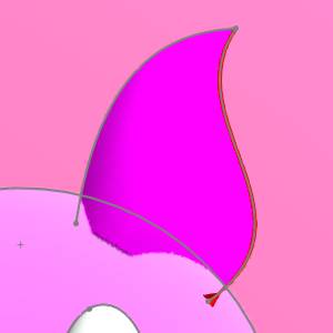
- Under Right Ear - Merge High, right-click Rail
1-Geometry and select Reverse Direction.
- Right-click Emboss
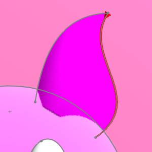
Model, and click Regenerate. The result is shown next.

Notice that with the rails moving in opposing directions, the result is twisted. - Under Right Ear - Merge High, right-click Rail
1-Geometry and select Reverse Direction.
- Right-click Emboss
Model, and click Regenerate to restore the model to its previous state.
Part 13) Emboss 2-Rail Sweep 12 - Left Ear
Insert and Edit the Feature
- Repeat the process of feature creation for the left ear.
- Click OK.
Select Feature Geometry
-
Repeat the process, listed for Emboss 2-Rail Sweep 11 - Right Ear, for the left ear using the Emboss 2-Rail Sweep - 12 item.
-
Use the outer ear entity as the first rail and the inner ear entity as the second rail. The cross section geometry direction is the same as for the right ear.
Generate the Emboss
-
Right-click
Emboss
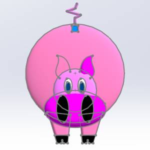
Model, and click Regenerate.
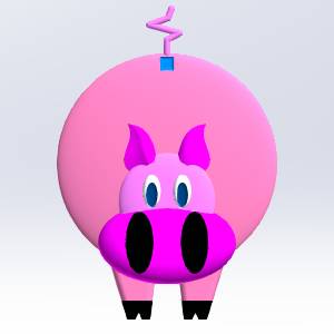
The model should appear as shown next.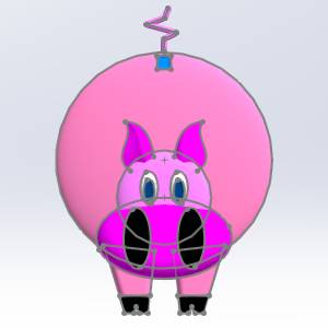
Hide the sketch
- In the Feature Manager Design Tree, right-click (-) Model, and select Hide.
The Sketch is hidden. 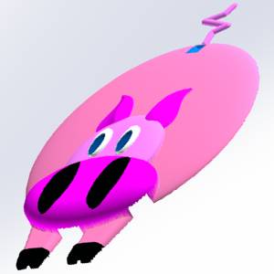
This concludes the tutorial.