How to Wrap an Emboss Model
Introduction
This topic explains the process and parameters used to wrap the model.
Generally, you should create the model as a flat (unwrapped) model and then wrap the model after you have created all of your features. This method may not always be followed, but it is used for this example. In this example, we are ready to wrap a finished model.
Example File
The BobCAD part file for this tutorial is available for download at:
http://www.bobcad.com/helpfiles.
If you are connected to the Internet, you can click the link provided
to download and save the Wrap
an Emboss Model Example 1.
In the provided example file, an Emboss from Component feature is already created.
Part 1) Open the Example File
-
in the
-
In the Open dialog box, select the folder in which you saved the example files.
-
Select Wrap an Emboss Model Example 1.
The file is opened and the model is displayed in the graphics area.
Part 2) Wrap the Model
The wrapping parameters are accessed in the Stock Parameters dialog box.
-
In the BobART tree, right-click
 Emboss Model, and click Create/Modify Stock.
The Stock Parameters dialog box is displayed. -
To turn on wrapping, select the
 Wrap
Model check box.
Wrap
Model check box.
All of the wrapping parameters are enabled.
Confirm that the Axis Origin is set to X0Y0Z0 and the Axis Direction is set to X Axis.
In the Zero Degree Location group, set the Y value to 0.00. -
To close the dialog box, click OK.

Notice that the model is moved to X0Y0Z0. You can also see that the diameter of the wrapped model is larger than needed.
Part 3) Create a Full Wrap Using the Model Size
You can use the size of the model/stock to create a full cylindrical wrap. The software calculates the value using the size of the stock, not just the embossed area. In this example, they are the same.
-
In the BobART tree, right-click
Emboss Model, and click Create/Modify Stock.
In the Wrapping Diameter group, click Full Cylindrical Wrap.
The software automatically calculates the value to create a fully cylindrical wrap based on the model size. -
To close the dialog box and update the changes, click OK.
The model is now a full cylindrical wrap. The Wrapping Diameter is measured to the stock surface (it does not use the height of the feature/model.)
You can see in the previous image that the top of the ring is actually at the bottom of the cylinder. This orientation may or may not be acceptable. To define what part of the model is placed at the top of the cylinder, you use the Zero Degree Location.
Part 4) Setting the Zero Degree Location
The Zero Degree Location defines what part of the flat model is placed at the zero degree location (top) of the cylinder. This distance is measured from the model origin perpendicular to the rotation axis.
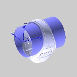
The following images show the zero degree location.
In the first image, the coordinate system represents the origin (lower-left corner) of the model and not the WCS. (This is done to show the direction of each axis.)


-
Right-click
Emboss
Model, and click Create/Modify
Stock. -
In the Zero Degree Location group, click Middle Line as Zero Degree.
Notice that the Y value is automatically set based on the size of the model.
This is half of the model length measured perpendicular to the rotation axis. The software divides the total length by 2.00. -
To close the dialog box and update the model, click OK.

Part 5) Setting the Axis Origin
The Axis Origin is used to move the location of the wrapped model in the Workspace. These parameters work together with the Axis Direction (rotation axis). The Axis Origin values define the center of rotation for the wrapped model along each axis, except for the value along the rotation axis. For example, with X-axis rotation (Axis Direction) the X-value of the Axis Origin defines the position of the model origin along the X-axis.
Currently the Axis Origin values are X0Y0Z0 with rotation around the X-axis. This means that the center of the wrapped model (from the stock surface) is at Y0Z0 and the origin of the model is aligned with X0.
-
Right-click
Emboss
Model, and click Create/Modify
Stock.
In the Axis Origin group, set the X value to 2.00.
Click OK.
Notice that the origin of the model is aligned with X
The remaining Y and Z values define the center of rotation for the model. -
Right-click
Emboss
Model, and click Create/Modify
Stock.
In the Axis Origin group, set the Y value to 2.000, and set the Z value to 1.000.
Click OK.


Part 6) Remove the Non-Emboss Area (Stock Surface)
-
Right-click
Emboss
Model, and click Create/Modify
Stock. -
Select the
Remove
Non-Emboss Area check box. -
To close the dialog box and update the model, click OK.

Part 7) Turning Off Wrapping
At any time during the creation process, you can unwrap the model and return it to the original location.
-
Right-click
Emboss
Model, and click Create/Modify
Stock. -
Clear the
 Wrap
Model check box to turn of wrapping.
Wrap
Model check box to turn of wrapping. -
Click OK to close the dialog box, and the model is returned to the unwrapped location.

This concludes the example.
Tip - How to Wrap a Model Twice
Using a combination of BobART features, you can actually wrap a model more than once. You can partially wrap the first model and then save it as a component. Next, you create an Emboss from Component feature, and then wrap the feature to create the second wrap.
-
A partial wrap is applied to the model.

-
The model is saved as a component.
-
In a new file, a feature is created using Emboss from Component.

-
The model is wrapped a second time.

The following image shows the same model. This time, a negative wrapping diameter is used on the first partial wrap. The negative wrapping diameter causes the raised areas of the model to appear inside of the wrapped model instead of the outside. The partial wrap and the result are shown next.