Assigning Fixtures for Multiple Setups Using Configurations
Introduction
Each of the machine setups in a milling job can have a unique fixture assigned to it. This example explains how to assign components, set in a particular configuration, as fixtures in the machine setups. In this example, once we assign the fixtures, we will also view the fixtures in simulation.
This example will have you:
- Assigning Fixture 1
- Switching the Configuration
- Assigning Fixture 2
- Switching the Configuration
- Assigning Fixture 3
- Simulate the Milling Job
Example Part
The part file for this example is available for download http://bobcad.com/helpfiles. If you are connected to the Internet, you can click the link provided to download and save the SlottedPart_and_FixtureSub3.zip file. After extracting the zip file, you can open the SlottedPart_and_FixtureSub3.sldasm assembly file to follow along with this example. In the example file provided, three Machine Setups have already been created, and completed.
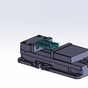
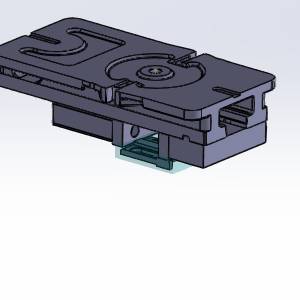
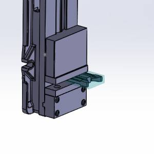
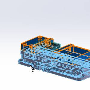
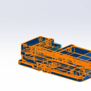
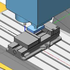
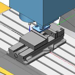
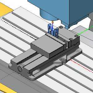
| Machine Setup 1 | Machine Setup 2 | Machine Setup 3 |
|
|
|
Important: If, when the assembly is open, the parts in the Feature Manager Design Tree show an ![]() icon, right-click
icon, right-click ![]() BowlingSignAssembly at the top of the Feature Manager Design Tree, and select Set Lightweight to Resolved. The part icons will then show an
BowlingSignAssembly at the top of the Feature Manager Design Tree, and select Set Lightweight to Resolved. The part icons will then show an ![]() icon, and you will then have access to the part features.
icon, and you will then have access to the part features.
Part 1) Assigning the Fixture
With everything in the job completed already, we could simply simulate, and post out the code. However, in order to see the fixture in the simulation, and check it for collisions, we will need to assign geometry as our fixture. With the Setup1 configuration active, we can simply assign the components in their current orientation as the fixture.
- Click on the
 CAM Tree - Manager tab.
 - Click the
 icon next to
  Machine Setup - 1 in order to expand it.
 - Right-click
 Fixture, and select Re/Select.
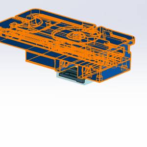
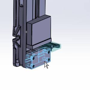
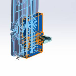
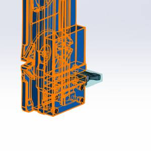
The Fixture dialog appears with focus on the Solid Body list. - Select each component of the vise.
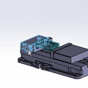
Note: In the images above the bolts on top of the fixed jaw, and the vise handle mount are not selected. Since the fixture selection is used to check for collisions in the simulation, you may choose to leave particular aspects of the vise assembly unselected.
- Click
 (OK).
(OK).
The Fixture dialog closes, and the icon is no longer seen in front of the Fixture item in the CAM Tree. This shows that geometry is currently assigned.
Part 2) Switching the Configuration
SolidWorks gives you the ability to create multiple configurations of the same parts, and switch between them. These configurations are how we specify the various orientations and positions of our vise to assign as a fixture.
- Click on the
 Configuration Manager tab.
 - Double-click on Setup2.
The components of the vise reorient to the active configuration.
Important: When creating an assembly, the first piece brought in is fixed in its location. It is important to have the intended workpiece as the fixed part.
Part 3) Assigning the Fixture
Now that we have switched to the second configuration, we can select the components of this configuration as the fixture of our second Machine Setup.
- Click on the CAM Tree - Manager tab.
- A message appears:
"The model geometry has been modified. Some machining features may no longer be valid, do you want to auto-update the CAM Tree?"
Click No.
The message disappears. - Click the icon next to Machine Setup - 2 in order to expand it.
- Right-click Fixture, and select Re/Select.
The Fixture dialog appears with focus on the Solid Body list. - Select each component of the vise.
- Click (OK).
The Fixture dialog closes, and theicon is no longer seen in front of the Fixture item in the CAM Tree. This shows that geometry is currently assigned.
Part 4) Switching the Configuration
We now switch to the third configuration, which will be associated with the fixture of our third Machine Setup.
- Click on the Configuration Manager tab.
- Double-click on Setup3.
The components of the vise reorient to the active configuration.
Part 5) Assigning the Fixture
Now that we have created that machine setup, we can select the configuration as our fixture.
- Click on the CAM Tree - Manager tab.
- A message appears:
"The model geometry has been modified. Some machining features may no longer be valid, do you want to auto-update the CAM Tree?"
Click No.
The message disappears. - Click the icon next to Machine Setup - 3 in order to expand it.
- Right-click Fixture, and select Re/Select.
The Fixture dialog appears with focus on the Solid Body list. - Select each component of the vise.
- Click (OK).
The Fixture dialog closes, and theicon is no longer seen in front of the Fixture item in the CAM Tree. This shows that geometry is currently assigned.
Part 6) Simulate the Milling Job
With the fixture assigned, we can now view it in the simulation.
- Right-click the
 Milling Job, and select Simulation.
The simulation launches. - Click
 Run.
Run.
As the simulation runs, notice the changes in the orientation of our vise. These are the various configurations we have assigned as our fixtures.
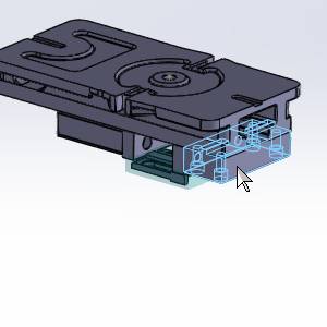
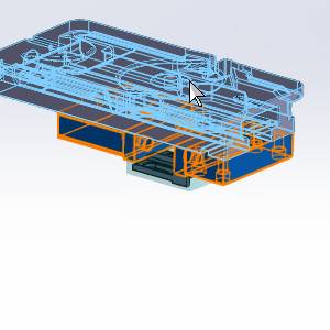
| Machine Setup - 1 | Machine Setup - 2 | Machine Setup - 3 |
|
|
|
- Click
 (Exit) at the top right of the simulation window to close the simulation.
This concludes this example.