How to Create a Corner Rounding Operation
Introduction
This topic explains the process of creating a Corner Rounding operation using the 2 Axis Wizard. You learn how to properly select geometry, set the depth, and define the tool data to create the operation for the outer and inner profiles of the example part. You can apply the information in this example to your own part (or just a rectangle).
Example
The following image shows the part used in this example with the machining origin set to the top of the part.
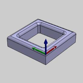
Part 1) Load the Tool Crib and Create the Feature
-
In the CAM Tree, right-click
 Milling
Tools and click Tool Crib.
In Tool Crib, click Add From Tool Library.
In the list on the left, under Mill, click Corner Rounding.
Note: If you select the Corner Rounding group in the Tool Crib before you click Add From Tool Library, the Select Tool dialog box then only displays Corner Rounding tools.
In the list on the right side, select the tool with the 1.125 Diameter and 0.3125 Corner Radius, and click OK.
In the Tool Crib, click OK.
-
In the CAM Tree, right-click
 Machine
Setup, and click Mill 2 Axis.
Part 2) Select the Feature Geometry
-
In the Geometry Selection dialog box, click Select Geometry.
Select the outer profile to assign to the feature as shown next.
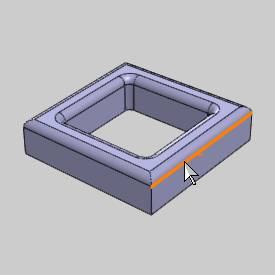
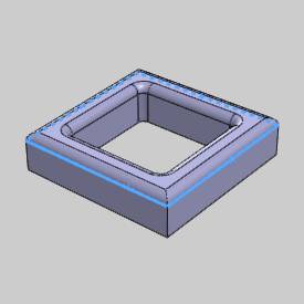
Note that you could also select the bottom surface edge of the part for this example, as long as you select the outer profile of the part. The Z-axis location of the selected geometry is not extremely important for this example because the depth of the feature is set using the Top of Feature and the Total Depth (as explained in Part 3). What is important is the machining origin location in reference to the target geometry, as the Top of Feature is the distance from the machining origin.
-
To confirm the selection, click
 (OK).
(OK). -
Click Next>> to go to the Feature settings.
Part 3) Define the Feature and Operation Parameters
-
In the Material Approach group, set the Rapid Plane and Feed Plane for the feature.
The Top of Feature was automatically set to 0.00 because the machining origin is placed at the top of the part model.
Tip: The Total Depth for the Corner Rounding operation is set in the operation Parameters page. The Total Depth in the Feature parameters is not used to set the depth of the Corner Rounding operation. This is done to allow you to create other operations, such as pocketing or profiling operations, in the same feature. This can be done because these operation types can use the same feature geometry.
Click Next>> to go to the Machining Strategy.
-
Click
 (Delete Operation) twice to delete
both operations from the Current
Operations list.
In the Available Operations list, select Corner Rounding, and click (Add Operation)
to add a single operation to the Current Operations list.
The Machining Strategy is defined.
Click Next>> to go to the Posting settings. -
Set the proper Work Offset # and click Next>> to go to the Tool settings.
-
In the Tool Data group, the proper tool data is already loaded from the tool in the Tool Crib that matched the operation type.
Tip: When you preload tools in the Tool Crib and then type values into the available System Tool parameters (Diameter, Small Diameter, and Corner Radius), the proper tool data is automatically loaded when there is a matching tool, including the tool holder assignment, tool number, and feeds and speeds values.
To learn more about defining a Corner Rounding tool, view The Corner Rounding Tool.
Click Next>> to go to the operation Patterns.
-
In the Patterns settings, the Standard pattern and SystemCompensation Left are selected.
Important: Tool compensation for the Corner Rounding tool uses the Small Diameter of the tool.
Click Next>> to go to the operation Parameters.
-
In the operation Parameters, you can set a side allowance or multiple steps, but most important here is the Total Depth for the Corner Round operation.
The Total Depth for the operation is usually the same as the Corner Radius of the tool.
If the tool has a Small Diameter Length, then this value must be added to the Corner Radius for the Total Depth.
For this example, set the Total Depth to 0.3125.
Click Next>> to go to the operation Leads.
-
In the Leads settings, a Parallel Lead-in is selected with a Length of 0.750.
Notice that the Lead-out is also set to the same parameters because the Same as Lead-in check box is selected.
For the remaining operation parameters, the default Sharp Corners is used (and the Machine Sequence doesn't apply to a single contour).
To learn more about all operation parameters, view The Corner Rounding Operation.
To create the feature, click Compute.
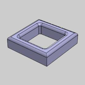
Notice that no toolpath is visible. This is because the current chain direction of the feature is placing the toolpath on the inside of the profile. This is resolved in the next part.
Part 4) Modify the Feature Chain Direction
After computing feature operations, is it always important to confirm the proper chain start point and direction (for each operation) as explained next.
-
To change the chain direction: in the CAM Tree, right-click
 Default
Chain Start Point, and click Modify.
When you modify the start point, you determine the operation start point and direction at the same time.
-
Click in the graphics area near the location that you want the start point.
The software moves the start point to the closest point along the chain based on the screen position of the mouse pointer.
If the start arrow is pointing in the wrong direction, you can click again in the same location to swap the direction.
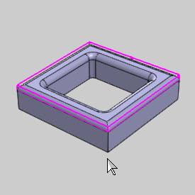
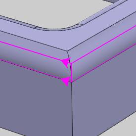
To confirm the new start point and direction,
click ![]() (OK).
(OK).
To reverse the direction only, without moving
the start point: right-click ![]() Default Chain Start Point, and
click Reverse.
Default Chain Start Point, and
click Reverse.
Tip: In this example, we changed the Default Start Point. This start point is applied to all operations in the feature. When you have more than one operation in the feature, you can also use the operation's start point item (contained below the operation in the tree) to define a different start point for each operation.
-
The start point is now set to the front corner and the direction is pointing to the left (clockwise).
The chain direction is now correct for the selected tool compensation settings.
To update the change, in the CAM
Tree, right-click ![]() Corner Rounding, and click Compute.
Corner Rounding, and click Compute.
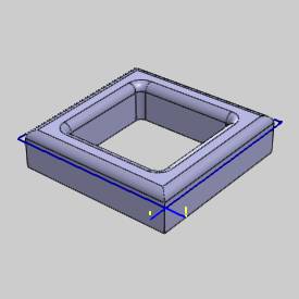
The toolpath is now on the proper side of the profile.
Part 5) Create the Second Feature
For this example part, there is also an internal feature that needs cut. A second feature is created because the inside feature requires a new geometry selection. Note that this feature could also contain a Pocket operation and/or Profile operation in addition to the Corner Rounding operation. For this example, we only create the Corner Rounding operation.
You can follow the same process, as explained for the outer feature, to the inner feature with just a few exceptions as shown next.
The only difference in the process for the inner feature from the outer feature, is the geometry selection.
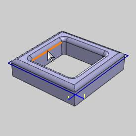
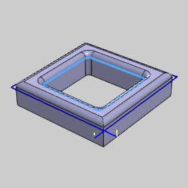
For the inner feature, a Blend lead-in and lead-out are defined to cause the entry and exit to use the same location inside the part.
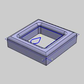
Tip: For the inside operation, because we are not leading in and out from a corner, you may want to specify an Overlap Amount (in the Lead-out group of the Leads settings) so that the lead-in and lead-out do not use the same entry and exit point. This can help to remove any scallop that may result when leading in and out from the same point.
Part 6) Simulate the Program
-
In the BobCAM menu, click
 Simulation.
(Alternatively, you can right-click ![]() Milling Job,
and click Simulation.)
Milling Job,
and click Simulation.)
To learn more, view Getting Started with Simulation.
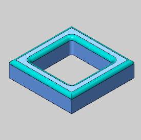
After simulating, the stock model appears as shown next.
-
To close the simulation window, in the BobCAM menu, click
 Exit Simulation.
Part 7) Post the Program
-
To post the code for the program, right-click
 Milling Job,
and click Post (or Post and
Save As).
The NC program (G-code) displays in the Posting Manager.
This concludes the example.
