Point and Arc Usage Example
Introduction
This topic explains the calculation options of the Hole Geometry Selection Manager for standard and multiaxis drilling: Point and Arc Usage (Arc Usage for multiaxis). These options determine how the software calculates the drilling toolpath when you select point, arc, or surface edge geometry. This information applies to both standard and multiaxis drilling, and some other tips are provided about selecting other geometry types, which also apply to cross drilling.
Part 1) Ignore Z
The Ignore Z option allows you to select geometry that is above or below the actual hole location and have the software ignore the Z-axis value of the geometry. This way you can set the top of feature and feature depth for each hole group yourself.
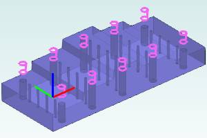
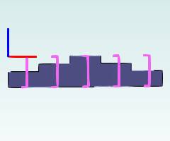
The following image shows an example drilling part and arc geometry that is selected from above the actual hole locations. The Ignore Z option is selected for this scenario.

When using this option:
- The Top of Feature defaults to 0.000
- The Feature Depth defaults to
- The Diameter is automatically set from the selected arcs
- (If points are selected, the Diameter defaults to
When we navigate to the Feature page of the wizard, we see that a single hole group is created because all of the holes share the same Diameter, Top of Feature, and Feature Depth. Note that one feature is created for each diameter.
After selecting the group in the Hole Groups list, the preview displays showing these settings as described.
The next step is to break the hole group and regroup the holes. For information on breaking and regrouping the holes, view the Break and Regroup Holes Example. After breaking and regrouping the holes for each level of the model, the Top of Feature and Feature Depth can be set for all hole groups.
Part 2) Use as Top
The Use as Top option allows you to select geometry that is at the top of the hole and have the software calculate the toolpath using the Z-axis location of the geometry.
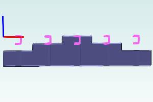
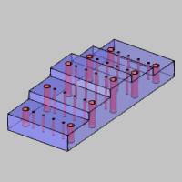
The following image shows an example drilling part and arc geometry that is selected at the top of each hole. (Note that this could be arcs or the surface edges themselves.) The Use as Top option is selected for this scenario.
When using this option:
- The Top of Feature is automatically set using the Z-axis location of each arc (or surface edge)
- The Feature Depth defaults to 0.500
- The Diameter is automatically set from the selected arcs
- (If points are selected, the Diameter defaults to 1.000)
When we navigate to the Feature page of the wizard, we see that three hole groups are created: one for each Top of Feature. (Note that two features are created, one for each diameter.)


The next step is to set the Feature Depth for each hole group. For the example part shown, two of the groups are broken to separate the groups that contains holes on opposite sides of the part. To learn more, view the Break and Regroup Holes Example.
Part 3) Use as Bottom
The Use as Bottom option allows you to select geometry that is at the bottom of the hole and have the software calculate the toolpath using the Z-axis location of the geometry.
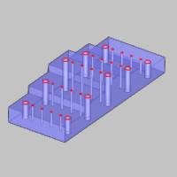
The following image shows an example drilling part and arc geometry that is selected at the bottom of each hole. (Note that this could be arcs or the surface edges themselves.) The Use as Bottom option is selected for this scenario.

When using this option:
- The Top of Feature defaults to 0.000
- The Feature Depth is automatically set using the Z-axis location of the selected geometry
- The Diameter is automatically set from the selected arcs
- (If points are selected, the Diameter defaults to
When we navigate to the Feature page of the wizard, we see that a single hole group is created because all of the holes share the same Diameter, Top of Feature, and Feature Depth. (Again, one feature is created for each diameter.)

The next step is to break the hole group and regroup the holes. For information on breaking and regrouping the holes, view the Break and Regroup Holes Example. After breaking and regrouping the holes for each level of the model, the Top of Feature and Feature Depth can be set for all hole groups.
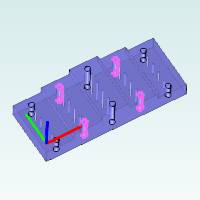
Part 4 ) Benefits of Selecting Cylindrical Surfaces
It is important to understand that selecting the cylindrical surfaces of the model directly for all holes allows the software to automatically set the Diameter, Top of Feature, and Feature Depth for you in the wizard. This allows the software to create hole groups using the actual dimensions from the part. This may be the most efficient method to use when you have solid or surface geometry.
When selecting cylindrical surfaces:
- The Top of Feature is automatically set using the top of the surface
- The Feature Depth is automatically set using the bottom of the surface
- The Diameter is automatically set using the diameter of the surface
Part 5 ) Summary
This example shows that the Point and Arc Usage calculation options provide you with all the options you need when selecting wireframe (point, arc, or surface edge) geometry for drilling. (Note that points cannot be selected for multiaxis drilling, so it is just Arc Usage for that type.)
The various calculation options are provided so that you can use the most efficient method for the part you are drilling. Selecting cylindrical surfaces is ideal when using a solid model, and the Point and Arc Usage options allow you to determine how the software calculates the toolpath for wireframe geometry types.
This concludes the example.