Work Offsets for Multiple Vices
Introduction
The purpose is to show how to use the work offset pattern to post a program that is programmed in work offset 1 (G54) to another two work offsets (G55 and G56).
Note: In this example, we will use the standard ISO work offsets of G54, G55, and G56. Some posts may be setup to use other codes for the work offsets. Using the Work Offset Pattern option will utilize the codes that have been setup to output in your post processor for your work offsets.
Example Part
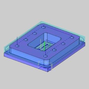
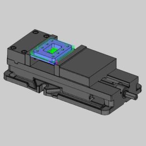
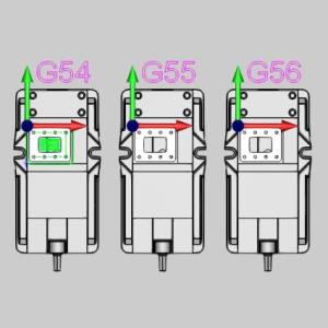
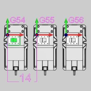
The following images show our example part, how it is held in the vice, and the additional two work offsets we intend to output. For this example, the fixture has already been assigned, and the first part already has toolpath applied using Work Offset 1.
|
Part |
Part in Vice |
All Work Offsets |
|
|
|
Example File Download
The part file for this example is available for download at:
http://bobcad.com/helpfiles.
If you are connected to the Internet, you can click the link provided
to download and save the Work Offset Pattern
This example highlights the following features of the BobCAM
- Work Offset Patterns
Part 1) Create the Work Offset Pattern
In this part we create the work offset patterns which will repeat our output program with each repetition utilizing the exact work offset value we specify here.
- Right-click on Machine Setup - 1 and choose Work Offset Pattern.
The Work Offset Pattern dialog launches. - In the Pattern Type group, select Translate.
Note: We could also use the Array option with zero copies in the Y Direction.
- In the Translate Parameters:
- Set the Copies to 2 in order to create one offset for G55, and another for G56.
- Set the X value in the Translate Amount group to
- Set the Copies to 2 in order to create one offset for G55, and another for G56.
Note: We use 14 because in this instance our vices are roughly 14 inches from G54 0.00 to G55 0.00. This distance has no effect on the output code, and is only utilized to show toolpath and simulate. The position of all work offsets are dictated at the machine.
- At the bottom of this section, click Generate Copies.
The work offset copies appear in the Generated Patterns section.
Note: Notice the first pattern is selected by default. In the following section, Parameters, we can see the values for the first generated pattern. Since we have our Start set to 2, and our Increment set to 1 in the Work Offset Numbering section of the dialog, our generated copies have work offsets of 2 (G55), and 3 (G56).
- Click OK.
Now, when the program is posted, the program will be repeated twice. The first time it will be repeated with Work Offset 2, which is usually a G55. The second time it will be repeated with Work Offset 3, which is usually G56.
Part 2) Simulate
With the work offset patterns created, we will verify them in the simulation.
- In the CAM Tree, right-click Milling Job, and select Simulate.
The simulation launches.
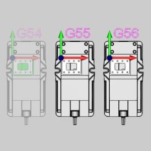
Notice the additional fixtures, and stock are now visible in the simulation.
View the simulation if you wish. - Exit the simulation.
Note: To adjust what is visible in the simulation, see the Simulation parameters in the lower left hand corner of the Work Offset Pattern dialog. These options give you the ability to show the patterned positions of the Stock, Fixture, and Workpiece, or not.
Part 3) Show the Toolpath
You may have noticed, when we first created the patterns, and exited the dialog, we did not see any toolpath. This is because, by default, the Blank Patterned Toolpath option is selected in the dialog. In this part, we deselect that option to allow the toolpath to be shown.
- Right-click on Machine Setup - 1 and choose Work Offset Pattern.
The Work Offset Pattern dialog launches. - In the first section, under Toolpath Display, deselect Blank Patterned Toolpath.
- Click OK.
The dialog closes, and the toolpath is visible.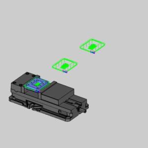
Congratulations! You have completed the Work Offsets for Multiple Vices Example.