Work Offsets for Tombstones
Introduction
The purpose is to show how to use the work offset pattern to post a program that is programmed in work offset 1 (G54) to several other locations (G55, G56, G57, ...etc) in a tombstone fixture.
Example Part
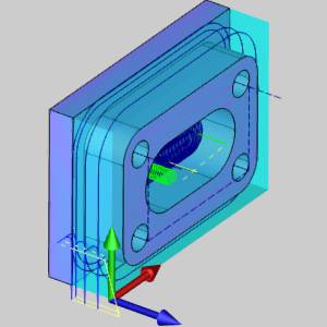
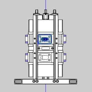
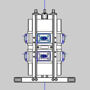
The following images show our example part, and how it is held in the tombstone. For this example, the first part already has toolpath applied using Work Offset 1, and the intention is to have our program output for the other seven work offsets as well.
Note: In this example, we will use the standard ISO work offsets of G54, G55, and G56. Some posts may be setup to use other codes for the work offsets. Using the Work Offset Pattern option will utilize the codes that have been setup to output in your post processor for your work offsets.
|
Part |
Part in Tombstone |
All Work Offsets |
|
|
|
Example File Download
The BobCAD part file for this example is available for download at:
http://bobcad.com/helpfiles.
If you are connected to the Internet, you can click the link provided
to download and save the Work Offset Pattern Tombstone
Tip: If you install a new machine by copying it to your MachSim folder with the software closed, you can open the software, open a file which uses that machine and immediately simulate. However if the software is already open when the machine is copied to your MachSim folder opening a file which uses the new machine will show the error: The machine used in this job does not exist in the system. Please choose a machine from the Job Current Settings. To correct this, simply right-click CAM Defaults and select Current Settings. Once the dialog opens, just click OK. The list of machines in the MachSim folder is now refreshed and the simulation can be run!
This example highlights the following features of the BobCAD-CAM software:
- Work Offset Patterns
Part 1) Create the Work Offset Pattern
In this part we create the work offset patterns which will repeat our output program with each repetition utilizing the exact work offset value we specify here.
- Right-click on Machine Setup - 1 and choose Work Offset Pattern.
The Work Offset Pattern dialog launches. - In the Pattern Type group, select Rotate.
- Under Toolpath Display, deselect Blank Patterned Toolpath.
- Under Simulation Parameters, deselect Pattern Fixture.
Note: We deselect the Blank Pattern Toolpath option to see the toolpath in the desired locations. By default the Pattern Workpiece option is cleared. This is good because in this part file we have a solid model patterned in the appropriate locations. Since there is only one fixture for all parts we must clear the Pattern Fixture option to avoid seeing multiple tombstones in the simulation.
- In the Rotate Parameters section:
- Leave the Angle at 90.0000.
- Set the Copies to 7.
- In the Rotation Axis group, select Pick Axis.
The Work Offset Pattern dialog hides, and the Work Offset Pattern Rotation Axis dialog opens in the Data Entry Manager. - Select the blue vertical line running through the tombstone.
The line is added to the Selected Geometry list. - Click OK.
The Work Offset Pattern dialog returns. - At the bottom of this section, click Generate Copies.
The work offset copies appear in the Generated Patterns section.
- Leave the Angle at 90.0000.
Note: We now have all of our copies wrapped around the tombstone and some sitting on top of each other, this would be fine to post the program properly, but to show the toolpath properly, or to view the cuts in the simulation properly, we need to move the last four copies down to the other parts.
- In the Generated Patterns section, click on number 5.
Note: In the Position and Orientation group of the Parameters section, notice the value listed under Origin(X: Y: Z Value). This is the position of the copy in relation to the Machine Setup. Each value is separated by a semicolon and represent X, Y, and Z respectively.
- In the Position and Orientation group of the Parameters section, change the Y value listed under Origin(X: Y: Z Value) to -6.8910.
Note: We use -6.8910 because, as you can see in the images below, that is the distance between G54 0.00 to G55 0.00. This distance has no effect on the output code, and is only utilized to show toolpath and simulate. The position of all work offsets are dictated at the machine.
- Repeat these last two steps for Generated Patterns 6, 7, and 8 as well.
- Click OK.
Part 2) Simulate
With the work offset patterns created, we will verify them in the simulation.
- In the CAM Tree, right-click Milling Job, and select Simulate.
The simulation launches.
Notice we have a single fixture, and multiple pieces of stock.
View the simulation if you wish. - Exit the simulation.
Congratulations! You have completed the Work Offsets for Tombstones Example.