How to Create Indexing Programs
Introduction
There are two methods that can be used to create programs with indexing. The first method uses Index Systems that are added to the CAM Tree. This method allows you to select geometry or UCS planes as the indexing plane. This is typically used with solid models and it is useful when the index angles are not known. When using this method, you can view the part indexing to the proper location in simulation. This method is explained first.
Note: Indexing is only available with the 4 Axis Standard and greater modules.
Example File
The BobCAD part file for this tutorial is available here C:\BobCAD-CAM Data\**Current Version**\Examples\Indexing.bbcd. In this example, you learn how create an indexed part.
Create Indexing Programs Using Index Systems
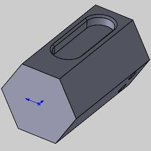
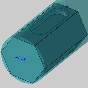
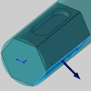
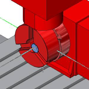
The Machine Setup in the CAM Tree is used to define the machining origin (work offset) of the part on the machine. To use Index Systems, you must first create stock for the part and define the Machine Setup. You then add an Index System to the Machine Setup in the CAM Tree. After adding an Index System, you select a plane to define the indexing position. Once the indexing plane is defined, milling features are added to the Index System. This tutorial is designed to explain the setup process. The part for this example is shown next.
Note: Indexing can also be accomplished using the Output Rotary Angle parameter that is available in the Posting page of the Milling Wizards. For this method, you use the Rotation Angle parameter to create the proper indexing in the posted program. The indexing of the part is not visible in simulation, it is only output in the posted NC program.
Part 1) Create the Job
- Create a New Job by either:
- In the CAM Job group, of the CAM ribbon, click
 New Job.
 - In the quick access toolbar of the CAM Tree Manager, click
 New Job.
 - In the CAM Tree Manager, right-click
 CAM Defaults, and select New Job.
- In the CAM Job group, of the CAM ribbon, click
Part 2) Select the Job Type and Machine
- With the Job Type set to the default Milling, click the down arrow under the Machine, and select the BC_4x_Mill.
Part 3) Create Stock for the Part
- In the Machining Job dialog, click Stock Wizard.
The Workpiece dialog appears, allowing you to select the workpiece to appear in the simulation.
This can be ignored, or the desired solid can be selected in the graphics area. - Whether a workpiece has been selected or not, click >> to move to the Stock Definition dialog.
The default Rectangular stock appears around the model. - Click
 in the Stock Type section to set the stock to a cylindrical shape.
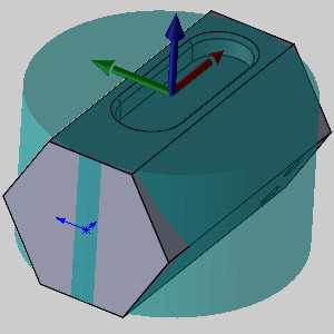
- Near the bottom of the dialog, in the Stock Orientation section, click the down arrow under Extrusion Direction, and select X Axis.
- Above that, in the Dimension / Offset group, set the Start Face value to 5.000.
The stock is now defined -
 next to go to the Machine Setup dialog box.
Part 4) Define the Machine Setup for the Part
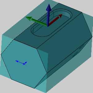
In the Machine Setup dialog box, the stock is outlined with entities that are automatically created to help you select the machining origin.
-
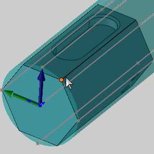
In the Coordinate System group, click in the Origin list to give it focus, and click on the back end of the edge of model as seen in the image below.
-
The default Clearance Plane value is used.
Note: The value set here is used for all features added to this Machine Setup in the CAM Tree.
The next step is to define the distance from the machine zero to the machining origin of the part, which is set on the top of the cylindrical stock, but for this example, we will skip that until later.
-
The Machine Setup for the part is now defined. To finish, click OK.
Tip: To hide
the stock from view while working, right-click ![]() Stock, and click Blank/Unblank.
Stock, and click Blank/Unblank.
Part 5) Add an Index System to the Machine Setup
Important: Before
adding milling features to an index system, you must define the indexing
plane as explained in this example. When adding milling features using
Index Systems, you must right-click the ![]() Index
System and not the
Index
System and not the ![]() Machine Setup.
This is the only way to have the proper angles set by the software. (If
you add a milling feature using the Machine Setup, the feature is not
added to the Index System.)
Machine Setup.
This is the only way to have the proper angles set by the software. (If
you add a milling feature using the Machine Setup, the feature is not
added to the Index System.)
-
To add an Index System, in the CAM Tree, right-click
 Machine Setup, point to Additional Functions, and click
Add Index.
Machine Setup, point to Additional Functions, and click
Add Index. -
This enables selection mode for you to select a planar face or surface.
Tip: If you do not have a planar face or surface to select, you can select a UCS, in the Index System Select dialog box, to set the index plane.
-
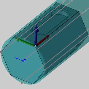
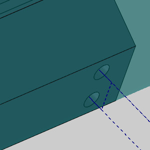
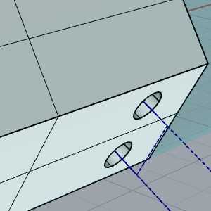
Click the face with the drill holes.
- The face is added to the Selected Geometry list, and a preview of the index system is displayed.
- Click OK.
The index system is set, and you are ready to add milling features.
Part 6) Feature Setup
- in the CAM
Tree, right-click
 Index System, and select Mill Drill Hole.
The Mill Hole Wizard appears. - Click Select Geometry.
The Mill Hole Wizard disappears, and the geometry picking dialog appears. - In the Data Entry Manager, the Selected Geometry list automatically has focus to allow you to select geometry.
Select the inner surfaces of the two holes.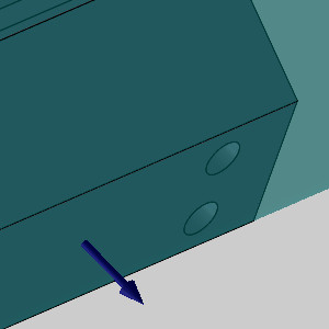
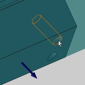
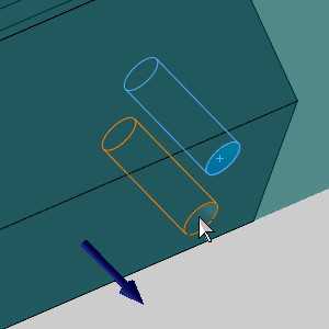
Each is added to the Select Geometry list. - Click OK.
The Mill Hole Wizard reappears.
Note: By selecting the surfaces and not the surface edge, the hole feature can recognize the proper depth to use for the holes.
- Click Next>> twice to go to the Machining Strategy page.
- Select the Hole Template.
- Since we are not concerned with drill settings in this example, click Compute.
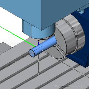
The Mill Hole Wizard disappears, and we can see proper toolpath on our part.
Part 7) Add another Index System to the Machine Setup
- To add an Index System, in the CAM
Tree, right-click Machine Setup, point to Additional Functions, and click
Add Index.
-
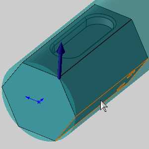
This enables selection mode for you to select a planar face or surface. - Click the face with the pocket.

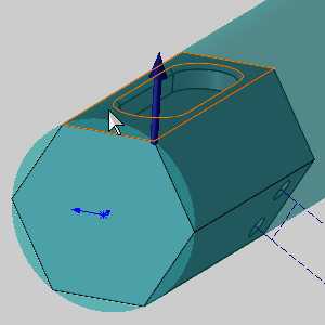
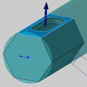
- The face is added to the Selected Geometry list, and a preview of the index system is displayed.
- Click OK.
The index system is set, and you are ready to add milling features.
To learn how to use toolpath patterns with index systems for repetitive tasks, view How to Create a Toolpath Pattern - 3D Rotate.
Part 8) Feature Setup
- in the CAM
Tree, right-click the second Index System, and select Mill 2 Axis.
The Mill 2 Axis Wizard appears. - Click Select Geometry.
The Mill 2 Axis Wizard disappears, and the index system appears on the part.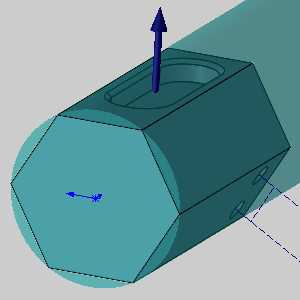
- In the Data Entry Manager, the Selected Geometry list automatically has focus to allow you to select geometry.
Select the bottom of the pocket.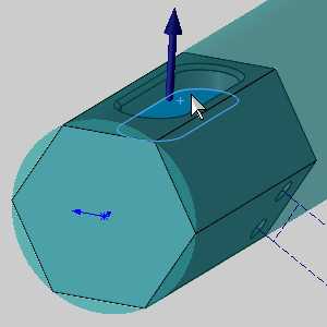
The face is added to the Select Geometry list, and the feature preview appears. - Click OK.
The Mill 2 Axis Wizard reappears. - In the tree on the left of the wizard, click Machining Strategy to jump to that page.
- In the Template list, select Pocketing.
- In the Current Operations list, select Profile Finish to highlight it, and click
 Delete.
The operation is removed from the current operations list. - In the tree on the left of the wizard, click
 Rough to jump to the tool page.
 - Update the Diameter value to 0.2500.
- In the tree on the left, click
 Parameters.
 - Update the Side Allowance to 0.0000.
- Click Compute.
The Mill 2 Axis Wizard disappears and the toolpath is visible.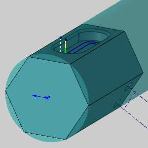
Part 9) Simulate
In this portion of the example we show the importance of setting the Work Offset in the Machine Setup. If you have Machine Simulation Pro, follow along. If not, there is no need to simulate.
- In the quick access toolbar of the CAM Tree Manager, click
 Simulate to launch the simulation.
The simulation launches. - In the Simulation group of the Simulation tab, ensure the
 Machine option is selected.
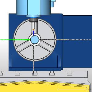
 - Notice the components colored in red signifying a collision.
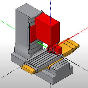
By zooming in, you can see the stock is completely inside of the chuck, and that is not centered.
This is because the machine zero we set at the beginning of the job will be placed at machine zero. To offset this, we must adjust our work offset. - In the Simulation group of the Milling ribbon, click
 Exit Simulation to exit the simulation.
Part 10) Adjusting the Work Offset
- In the CAM
Tree, right-click Machine Setup, and select Edit.
The Machine Setup dialog launches in the Data Entry Manager. - In the Layers Manager, right-click the Dimensions layer, and select
 Show Layer.
The dimensions become visible. - Click Work Offset at the bottom of the Data Entry Manager.
The Work Offset dialog launches.
We want to enter the values that show how the Machine Setup has moved from the WCS, which is the center of rotation on our machines.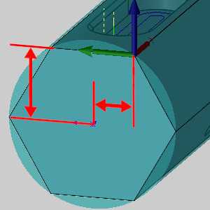
- We can see in the dimensions, we need to adjust the Y, and Z values to center the stock in the chuck, and we need to add a negative X value to pull it out of the chuck.
In the Work Offset dialog, change the values to:
X = -7.000
Y = -0.500
Z = 0.866
Note: Notice all these values are referencing the location of the machine setup from the World Coordinate System. Since our stock is eight inches in length, we set the X value to -7 in order to keep an inch inside the chuck.
Part 11) Simulate
- Simulate the part once more and notice our stock is as it should be.
- Exit the Simulation.
Part 12) Post the Program and Confirm the Output
After creating all of the necessary features, setting the proper Rotation Angle to output, and computing the toolpaths, you post the NC program to confirm the output.
-
In the CAM Tree, right-click
 Milling Job, and click Post.
The program is displayed in the Posting Manager. -
Check the program and confirm that the proper rotary-axis values are output.
This concludes the example.