How to Create Indexing Programs
Introduction
There are two methods that can be used to create programs with indexing. The first method uses Index Systems that are added to the CAM Tree. This method allows you to select geometry or UCS planes as the indexing plane. This is typically used with solid models and it is useful when the index angles are not known. When you simulate using this method, you can view the part indexing to the proper location. This method is explained first. The second method, using Output Rotary Angle, does not use index systems. This method creates indexing that is only output in the NC program, meaning that the indexing is not visible during simulation.
Note: Indexing is only available with the 4 Axis Standard, 4 Axis Pro, 5 Axis Standard, and 5 Axis Pro modules.
Method 1) Create Indexing Programs Using Index Systems
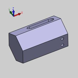
The Machine Setup defines the machining origin (work offset) of the part on the machine. To use Index Systems, you must first create stock for the part, and define the Machine Setup. You then add an Index System to the Machine Setup in the CAM Tree. After adding an Index System, a plane is selected to define the indexing position. Once the indexing plane is defined, milling features can then be added to the Index System. This tutorial is designed to explain the setup process. The part for this example is shown next.
Part 1) Create Stock for the Part
-
To open the Stock Wizard, in the
 CAM Tree, right-click
  Stock and click
Stock Wizard.
 -
In the Stock Specification, click
 Cylindrical.
 -
In the Stock Orientation group, under Extrusion Direction, click the arrow and select X Axis.
-
In the Offset group, in the Start Face Offset box, type 2.000.
Click Calculate Stock.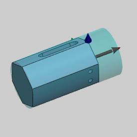
-
The stock is now defined, click
 Next
to go to the Machine Setup.
Part 2) Define the Machine Setup for the Part
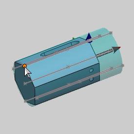
When you open the Machine Setup, the stock is outlined with entities that are automatically created to help you select the machining origin.
-
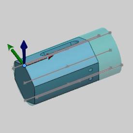
In the Origin group, click in the PickOrigin box, and click the point on the top-left side of the cylinder. The machining origin is now defined.
-
In the Other group, the default Clearance Plane value is used. (The value set here is used to automatically set the default values for features added to this Machine Setup in the CAM Tree.)
-
The next step is to define the distance from the machine zero to the machining origin of the part (that was just set to the top of the cylindrical stock). In the Work Offset group, in the Z box, type 2.00. This defines the center of rotation for the part and is required for proper simulation and posted code.
-
The Machine Setup for the part is now defined. To finish, click
 OK.
OK.
Tip: To hide
the stock while working, right-click ![]() Stock
and click Blank.
Stock
and click Blank.
Part 3) Add an Index System to the Machine Setup
-
To add an Index System to the Machine Setup: in the
 CAM Tree,
right-click
  Machine
Setup, point to Additional
Functions and click Add Index.
The Index System is added below the Machine Setup. -
To define the rotation angle for the Index System, right-click
 Index System and click Re/Select.
The Selection Manager displays.
Click the first face of the part. (If you do not have a planar face or surface to select, you can also select a Plane to set the index plane.)
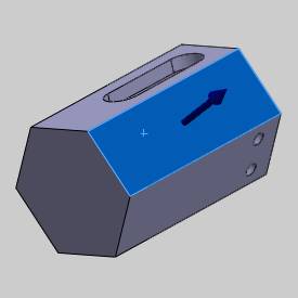
Notice that the index system indicator is pointing out away from the selected surface. This indicator represents the Z-axis of the index.
In the event that the index system indicator is pointing in the wrong direction, you can click Reverse to flip the Z-axis direction of the index system.
Note: When you select a plane or surface to set the index location, the plane/surface becomes the Z-axis zero for setting the feature parameters.
-
To confirm the selection, click
 OK.
OK.
If you click the Index System in the
  CAM
tree, the selected surface displays.
 -
At this point you are ready to add milling features to the Index System. For the purposes of this example, you continue adding index systems.
To add another Index System, repeat steps 1 through 3.
This time, select the next face or index of the part.
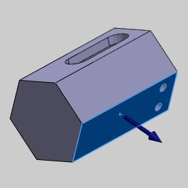
-
You repeat this process for each side of the part.
Once
you have defined the plane for an index system, you are ready to add milling
features to that index system.
-
You must follow this process of defining the Machine Setup, adding an Index System, and selecting a surface or UCS to set the proper angle before creating a feature for an Index System.
This way when you add milling features to each Index System, the indexing angle is automatically set for each feature.
Important: Before adding milling features to an index system, you must define the indexing plane as explained in this example. When adding milling features using Index Systems, you must right-click the Index System and not the Machine Setup. This is the only way to have the proper angles set by the software. If you add a milling feature using Machine Setup, then the feature is not added to the Index System.
This concludes Method 1.
To learn how to use toolpath patterns with index systems for repetitive tasks, view How to Create a Toolpath Pattern - 3D Rotate.
Method 2) Creating Indexing Programs without Index Systems
Indexing can also be accomplished using the Output Rotary Angle parameter that is available in the Posting page of the Milling Wizards. For this method, you use the Rotation Angle parameter to create the proper indexing in the posted program. The indexing of the part is not visible in simulation, it is only output in the posted NC program. Next we examine how to create a program to cut one pocket and two holes at different index locations for the part used in Method 1.

Part 1) Feature Setup
For this example, imagine that you don't have a solid model. The part that you are machining is already faced, and the pocket and holes are the only remaining operations. Because there are only two basic operations to create, we use sketch geometry. You must define the stock and machine setup for the part. The stock used for this example is the same as that created in Method 1. This time the machining origin is placed on a sketch that represents the edge of the face (which is now the top of part) instead of at the top of the cylindrical stock.
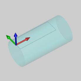
-
When defining the Machine Setup, be sure to set the proper Work Offset values as shown in Method 1.
For this example, the Z value is set to 1.732.
This sets the distance from the machine zero to the machining origin, which defines the center of rotation for the part. -
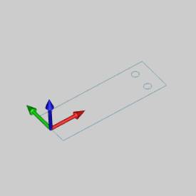
A sketch is created for the pocket geometry.
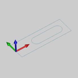
-
A separate sketch is created for the two holes.
-
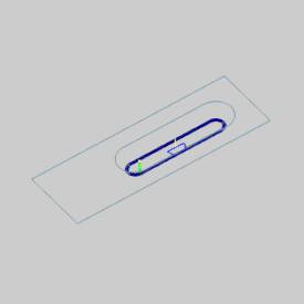
When you create the 2 Axis feature, in the Posting page of the wizard, select the
 Output
Rotary Angle check box.
 -
In the Rotation Angle box, type the appropriate indexing angle. For this example, the 2 Axis feature is output at 0.000 degrees.
Important: Because sketch geometry is being used it is important to enter the proper Depth value for the feature.
-
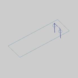
When you create the Hole feature, in the Posting page of the wizard, select the
 Output Rotary Angle check
box.
 -
In the Rotation Angle box, type the appropriate indexing angle. For this example, the Mill Hole feature is output at 240.000 degrees.
In the following image, the 2 Axis feature geometry and toolpath are hidden from view to only show what is used for the Hole feature.
Part 2) Post the Program and Confirm the Output
After creating all of the necessary features, setting the proper Rotation Angle to output, and computing the toolpaths, you can post the NC program to confirm the output.
-
In the
 CAM
Tree, right-click
  Milling Job and click Post.
The NC program displays in the Posting Manager.
 -
Check the program and confirm that the proper rotary-axis values are output.
You can then right-click anywhere in the Posting Manager and click Save As if you want to save a copy to a location other than the default.
This concludes the example.
