How to Create a Multiaxis Parallel to Multiple Curves Feature
Introduction
This tutorial explains how to create a Parallel to Multiple Curves feature. The feature creates cuts that are parallel to the selected edge curves and applied to the selected drive surfaces.
Example File
The SolidWorks part file for this tutorial is available for download at: http://www.bobcad.com/helpfiles. If you are connected to the Internet, you can click the link provided to download and save the Parallel to Multiple Curves Example 1.SLDPRT zip file. After extracting the zip file, you can then open the example file to use with this tutorial. In the example file provided, the stock and Machine Setup are already defined for the part. The part is simulated using the BC Table Table machine.
In this example, you learn how to apply a toolpath using multiple edge curves to finish the bottom of multiple pockets with angled walls. You learn how to change the default tool orientation using a tilting strategy with some special notes on handling a tool axis that is parallel to the surface normal of the selected drive surfaces.

Part 1) Add the Feature
-
In the Property Manager, click the CAM Tree tab.
-
Right-click
 Machine
Setup and click Mill Multiaxis.
Machine
Setup and click Mill Multiaxis. -
In the Multiaxis Wizard, select Surface and click Parallel to Multiple Curves.
-
Click Next>> to go to the Posting dialog box.
Part 2) Define the Posting Parameters
-
The Work Offset # is automatically set to the value defined in the Machine Setup dialog box.
You can change the value here to update the Work Offset # for the feature. -
Click Next>> to go to the Multiaxis Posting dialog box.
Part 3) Define the Multiaxis Posting Parameters
-
Notice, at the top of the dialog box, that the Use Machine Settings check box is selected.
This means that the Multiaxis Posting parameters for the feature use the same parameters as the machine that is selected in Current Settings.
You can clear the Use Machine Settings check box to define the Multiaxis Posting parameters of the feature separately from the current machine settings.
An example using is explained later. -
Click Next>> to go to the Tool page.
Part 4) Define the Tool Parameters
-
In the Tool Data group, set the Diameter to 0.50, and the Corner Radius to 0.25.
-
To assign a tool holder, click Assign Tool Holder.
In the Milling Tool Holder Library, in the CAT 40 Holder list, click 0.5 inch I.D. Arbor CAT 40.
Click OK. -
Click Next>> to go to the Parameters dialog box.
Part 5) Select Geometry
-
To define the curves that are used to create the parallel cuts, in the Pattern group of the Surface Paths tab, click Edge Curves.
-
In the graphics area, click
 to expand the
  Feature
Manager design tree.
Feature
Manager design tree.
In the design tree, click the Edge Curves feature.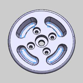
-
To confirm the geometry selection, click
 OK.
OK. -
To define the surfaces being machined, click Drive Surfaces.
In the graphics area, select the bottom of each pocket as shown next.
-
To confirm the geometry selection, click
OK.
The geometry selections are now complete.
Part 6) Define the Parameters
-
In the Area group, next to Type, select Determined By Number of Cuts.
In the Number of Cuts box, type 1. -
In the Sorting group, next to Cutting Method, select One Way.
Next to Direction for One Way Machining, select Climb. -
At the top of the dialog box, click Link.
At the bottom of the Link tab, click Retracts. -
In the Clearance Area group, confirm that the Height is set to 2.00.
This value is automatically set using the value previously defined in the Machine Setup dialog box. This value is only read from the Machine Setup when the feature is created. Existing features don't update if you change the Clearance value in the Machine Setup. You can change the Clearance value for Multiaxis features at any time in the Retracts dialog box.
To close the dialog box, click OK. -
To calculate the toolpath, at the bottom of the Multiaxis Wizard, click Compute.
The result is shown next with the part model made transparent to better view the toolpath.
Tip: To make
a toolpath easier to view, click the icon (or the name) of the operation
in the CAM Tree. This is like applying bold to the toolpath display. For
this example, in the CAM Tree, click ![]() Multiaxis.
Multiaxis.

The toolpath shows that the entry into each pocket is normal to the surface, which in this case, is parallel to the Z-axis.
The next step is to edit the feature and add a tilt angle.
Part 7) Edit the Feature and Tool Axis Control
-
When you computed the toolpath, the
 Multiaxis feature was added to the
  CAM Tree.
To edit the feature, right-click FeatureMultiaxis, and click Edit.
The Multiaxis Wizard displays. -
On the left side of the dialog box, click Parameters.
-
At the top of the dialog box, click Tool Axis Control.
-
Next to Tool Axis Will, select the tilting strategy, Tilted with the Angle.
In the Tilt Angle box, type 30.50.
Set the tilt axis to Z-axis.
Because the surface normal direction and the selected tilt axis are parallel, the defined tilt angle creates a condition where the tool axis crosses the tilt axis. (If you computed the toolpath now, there would be no change to the toolpath.)
To handle the tool axis crossing the tilt axis, select the Tool
Axis Crosses Tilt Axis check box.
Tool
Axis Crosses Tilt Axis check box. -
To apply the changes to the feature, click Compute.
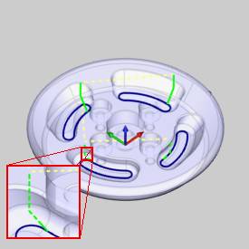
The result is shown next.
You can see the change in the entry/plunge move into each pocket in the toolpath display (green).
You can also see that the toolpath moved from the exact edge curve towards the inside of the part because of the new tool orientation.
Part 8) Simulation
-
The next step is to simulate the program to look for any necessary changes.
-
In the BobCAM menu, click
 Simulation.
For help with simulation, view Getting Started with Simulation.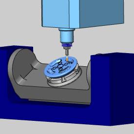
-
To close simulation, in the BobCAM menu, click
 Exit Simulation.
Adjust the Machine Table Rotation
When you simulate the program, the machine table is sometimes rotated in a way that doesn't allow you to view the part without rotating the view of the machine. You can change the Angle Pair settings for the feature to modify the table rotation used in simulation and in the posted code.
- To edit the feature, in the CAM
Tree, right click FeatureMultiaxis,
and click Edit.
- Click the
Multiaxis Posting icon in the tree.
- Clear the Use
Machine Settings check box.
- In the Angle
Pair group, next to Use,
select Other Solution.
When you simulate the program again, you can now view the part being cut from the opposite side of the machine.
The table is rotated to use the other solution to the rotation angles of the primary and secondary rotary axes (angle pair). This changes the posted output of the program as well as the simulation.
Tip: You don't have to compute the toolpath to update this setting for simulation, but you must Post the program to update the code if has already been posted.
This concludes the tutorial.