How to Create a Port Machining Operation 2
Introduction
This tutorial explains how to create Port Machining toolpath. This feature requires the selection of the port machining surfaces and may or may not require a spline curve defining the center of the port and check surfaces.
Example File
The part file for this tutorial is available for download at: http://www.bobcad.com/helpfiles. If you are connected to the Internet, you can click the link provided to download and save the Port Machining Example 2.SLDPRT zip file. After extracting the zip file, you can then open the example file to use with this tutorial. In the example file provided, the Tool Crib is already equipped with the necessary tools and the stock and Machine Setup are already defined. The part also has some initial rough and finish work completed which makes way for the roughing and the finishing of the ports themselves. The part is simulated using the BC_Porting_5x_HeadTable machine.
In this example, you create toolpaths that can be used to rough and finish the inside of a port.

Part sections
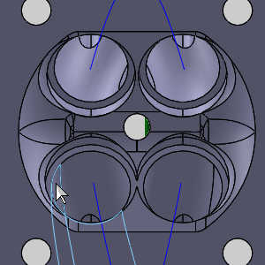
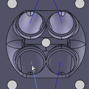
In order to keep things clear, we will be referring to the ports by their position when viewed from a top view.


Top view:
-
1) Top Right
-
2) Top Left
-
3) Bottom Left
-
4) Bottom Right
Part 1) Create the group structure
-
 CAM Tree tab
-
Right-click
 Machine
Setup, hover over Additional Functions, and click Add Group.
Machine
Setup, hover over Additional Functions, and click Add Group.
A group is added to the CAM Tree. Features can now be dragged into this group to assist in organization. -
Repeat this process to add another group to the CAM Tree.
-
Right-click the first group and select Add Child Group.
-
Add another child to the first group.
-
Add two children to the second group as well.
There should now be two groups, each with two child groups, in the CAM Tree.
Part 2) Name the groups
-
Right-click the first main group and select Rename.
-
Update the name to Bottom and press Enter.
-
Right-click the second main group and select Rename.
-
Update the name to Top and press Enter.
-
Rename the child groups so that each main group has a Rough child group, and a Finish child group.
Part 3) Roughing the bottom left (full)
Step 1) Create the first feature
-
Right-click
Machine
Setup and click Mill Multiaxis. -
In the Multiaxis Wizard, click Port Machining.
-
Click Next>> to go to the Posting dialog box.
Step 2) Define the Posting Parameters
-
The Work Offset # is automatically set to the value defined in the Machine Setup dialog box.
You can change the value here to update the Work Offset # for the feature. -
Click Next>> to go to the Multiaxis Posting dialog.
Step 3) Define the Multiaxis Posting Parameters
-
Notice, at the top of the dialog box, that the Use Machine Settings check box is selected.
This means that the Multiaxis Posting parameters for the feature use the same parameters as the machine that is selected in Current Settings.
You can clear the Use Machine Settings check box to define the Multiaxis Posting parameters of the feature separately from the current machine settings.
An example usage is explained later. -
Click Next>> to go to the Tool page.
Step 4) Select the Roughing Tool
-
Click the Tool Crib button.
The Tool Crib dialog appears. -
Select the LOLLIPOP tool type on the left of the dialog to show the lollipops available in the Tool Crib.
-
Highlight the 1/2" lollipop and click OK.
The Tool Crib dialog disappears. -
Update the Protrusion Length to 3.2500.
-
Click Next>> to go to the Parameters.
Step 5) Surface paths
-
In the Pattern group, select Roughing from the list.
-
In the Part definition group, click the ellipses button next to Machining surfaces.
The Mill Multiaxis Wizard disappears, and the Re/Select Geometry dialog opens allowing you to select the required geometry. -
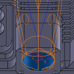
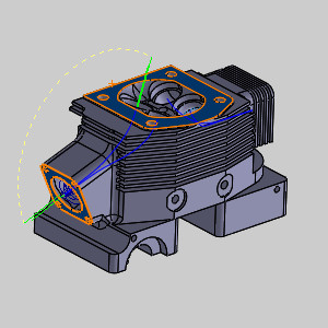
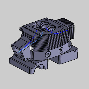
Select each the surfaces which comprise the bottom port.
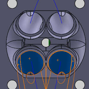
For the time being ensure the surface, seen in two different angles in the images, below is left out.
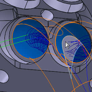
Rotate the part to select the remaining surfaces in the front.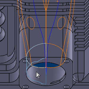
-
Click OK.
The Mill Multiaxis Wizard returns. -
Set the Offset value to 0.02.
-
Deselect the Automatic spine check box.
-
Click the ellipses button that appears with the Spine.
The Mill Multiaxis Wizard disappears, and the Re/Select Geometry dialog opens allowing you to select the required geometry. -
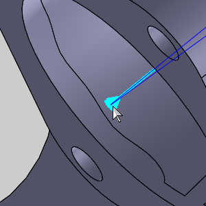
Click the spline on the left to assign it as the Spine geometry.
-
Click OK.
The Mill Multiaxis Wizard returns. -
In the Surface quality group, set the Cut tolerance to 0.001.
-
In the Stepover group, set the Maximum stepover and the Depth step to 0.2.
Step 6) Gouge check
-
Click the Gouge check tab.
-
In the Clearance values group, set the Shaft value to 0.03.
Important: The clearance value of the Shaft should always be larger than the offset (allowance) being used by.
Step 7) Link
-
Click the Link tab.
-
In the Clearance group, set each of the following to Auto in order to let the operation calculate the appropriate values for each:
-
Radius
-
Direction
-
Through
-
-
Click Compute.
Tip:
If you are using the Auto Blank New Items option in the CAM page of the Settings dialog, click the operation to view the toolpath. Switch to a
Step 8) Simulation
-
To view the program, in the Quick access menu of the CAM Tree, click
 Simulation.
 -
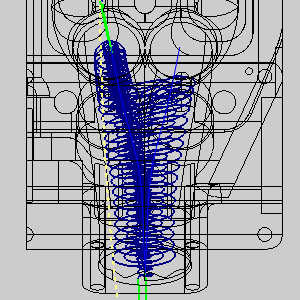
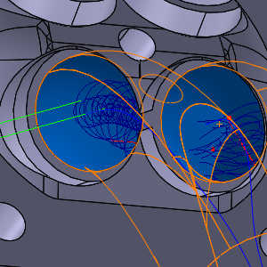
Click Play to view the operations in simulation.
This will allow you to ensure this operation is free of collisions and to check the deviation report to verify removal of all the material.
Notice the port operation is beginning from the bottom of the part.
Tip: You can also use the Next Op button to skip forward by operation, you could click on a particular Op. number in the Move List tab, or just drag the progress bar to the end of the simulation.
-
Once the simulation is finished click in the Analysis tab and choose Deviation from the drop down list.
-
Click
 Min/Max Detection, and then
  Refresh Cutsim to view the deviation report.
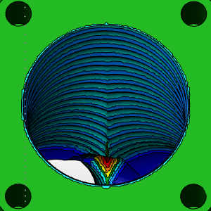
Notice the gouge in the port. -
To close simulation, in the
 Exit Simulation.
 -
In the File menu, click Save.
Step 9) Updating the feature geometry
-
Expand the Geometry folder of the feature and right-click Machining Surface/Mesh.
The Mill Multiaxis Wizard disappears, and the Re/Select Geometry dialog opens with the currently selected geometry already in the list. -
Select the surface we left out of the selection earlier.
-
Click OK.
-
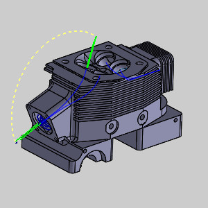
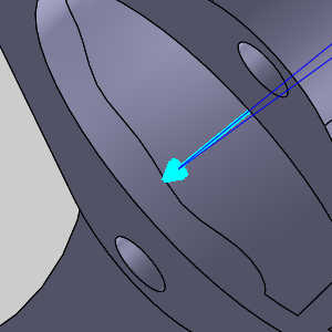
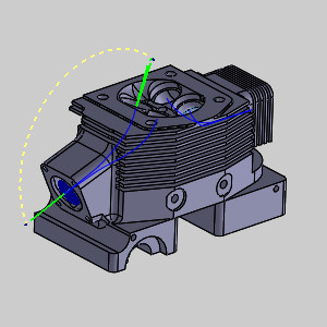
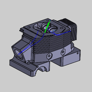
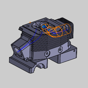
In the Geometry folder of the feature, right-click Port Spine and select Modify.
Notice the direction of the arrow on the spine we assigned for the feature.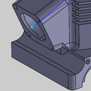
This arrow indicates the direction of the feature from the top to the bottom, and needs to be flipped in this case. -
Click
-
Click OK.
-
Right-click the feature and select Compute All Toolpath.
Step 10) Simulation
-
To view the program, in the Quick access menu of the CAM Tree, click
Simulation. -
Click Play to view the operation in simulation.
Notice the port operation is beginning from the top of the part now that we have switched the direction of the spine. -
Once the simulation is finished click in the Analysis tab and choose Deviation from the drop down list.
-
Click
Min/Max Detection, and then Refresh Cutsim to view the deviation report.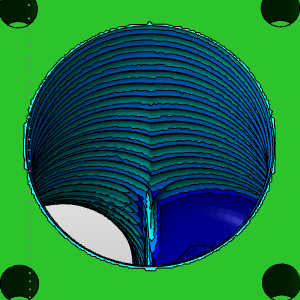
Notice the gouge inside the port has been correct. However, notice we now have a gouge on the top of our part.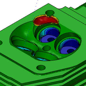
-
To close simulation, in the
Exit Simulation. -
In the File menu, click Save.
Step 11) Add check surfaces
-
Right-click the feature and select Edit.
-
Click Parameters to go to the Surface paths page.
-
Click the Gouge check tab.
-
In the last group, select the Check surfaces check box.
An ellipses button appears. -
Click the ellipses button to open the
-
Select the surfaces seen in the images below, as these would be the most commonly gouged.

-
Click OK.
The Mill Multiaxis Wizard returns. -
Click Compute.
Note: At this time, you could double check the simulation to ensure your check surfaces are eliminating the gouges found.
Step 12) Organize the CAM Tree
-
Right-click the feature and select Rename.
-
Update the feature name to Rough Left Both Mid, to indicate this is a Rough operation on the Left port, coming from Both sides which are meeting in the Middle.
-
Press Enter.
-
Drag and drop the feature into our Bottom group folder.
The feature is now contained in the Bottom group folder. -
Drag and drop the feature into our Rough group folder.
-
Right-click the feature and select Blank/Unblank Toolpath.
The toolpath is hidden. -
Click the small arrow next to the feature to collapse it.
Part 4) Roughing the bottom right (upper)
Step 1) Copy the first rough
-
Right-click the Rough Left Both Mid feature and click Copy with Geometry.
This copies every parameter of the feature as well as all geometry assigned to the feature. -
Right-click
Machine
Setup and click Paste Feature.
The feature appears in the tree. -
Right-click the pasted feature and select Rename.
-
Update the name to Rough Right Top Max and press Enter.
-
Drag and drop the feature into our Bottom group folder.
The feature is now contained in the Bottom group folder. -
Drag and drop the feature into our Rough group folder.
Step 2) Update the Surface paths parameters
-
Right-click the new feature and select Edit.
The Mill Multiaxis Wizard appears. -
Click Parameters to go to the Surface paths page.
-
In the Part definition group, click the ellipses button next to Spine.
The
-
-
Select the spine for the right port.
The geometry is added to the Selected Items list. -
Click OK.
The Mill Multiaxis Wizard returns. -
In the Area group:
-
Set the Output type to Top.
-
Set the Machine to option to Max from Top.
-
-
Click Finish.
-
In Geometry folder of the feature, right-click Port Spine, select Modify, and update the direction as we did in the first feature.
-
Click OK to confirm and return to the CAM Tree.
-
Right-click the feature and select Compute All Toolpath.


Part 5) Finishing the bottom left (full)
Step 1) Paste the first rough
-
Since the first rough feature has already been copied with geometry, right-click
Machine
Setup and click Paste Feature.
The feature appears in the tree. -
Right-click the pasted feature and select Rename.
-
Update the name to Finish Left Both Mid and press Enter.
-
Drag and drop the feature into our Bottom group folder.
The feature is now contained in the Bottom group folder. -
Drag and drop the feature into our Finish group folder.
Step 2) Update the Surface paths parameters
-
Right-click the new feature and select Edit.
The Mill Multiaxis Wizard appears. -
Click Parameters to go to the Surface paths page.
-
Update the Pattern to Finishing around.
-
In the Part definition group, click the ellipses button next to Machining surfaces.
The Mill Multiaxis Wizard disappears, and the -
In this case, we only need to deselect the extra surface we added for the roughing passes.
-
Click OK.
The Mill Multiaxis Wizard returns. -
In the Part definition group, set the Offset value to 0.
-
In the Stepover group, set the Maximum stepover value to 0.03.
-
Click the Gouge check tab.
-
In the Clearance values group, set the Shaft value to 0.01, and the Arbor value to 0.05.
-
Click Compute.
Part 6) Finishing the bottom right (upper)
Step 1) Copy the second rough
-
Right-click the Rough Right Top Max feature and click Copy with Geometry.
This copies every parameter of the feature as well as all geometry assigned to the feature. -
Right-click
Machine
Setup and click Paste.
The feature appears in the tree. -
Right-click the pasted feature and select Rename.
-
Update the name to Finish Right Top Max and press Enter.
-
Drag and drop the feature into our Bottom group folder.
The feature is now contained in the Bottom group folder. -
Drag and drop the feature into our Finish group folder.
Step 2) Update the Surface paths parameters
-
Right-click the new feature and select Edit.
The Mill Multiaxis Wizard appears. -
Click Parameters to go to the Surface paths page.
-
Update the Pattern to Finishing around.
-
In the Part definition group, click the ellipses button next to Machining surfaces.
The Mill Multiaxis Wizard disappears, and the -
In this case, we only need to deselect the extra surface we added for the roughing passes.
-
Click OK.
The Mill Multiaxis Wizard returns. -
In the Part definition group, set the Offset value to 0.
-
In the Stepover group, set the Maximum stepover value to 0.03.
-
Click the Gouge check tab.
-
In the Clearance values group, set the Shaft value to 0.01.
-
Click Compute.

Step 3) Simulation
-
To view the program, in the Quick access menu of the CAM Tree, click
Simulation. -
Click Play to view the operations in simulation.
Even without the deviation report we can see the middle is not finished.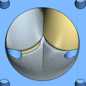
-
To close simulation, in the
Exit Simulation. -
In the File menu, click Save.
Step 4) Updating the first finish
-
In the CAM Tree, right-click Finish Left Both Mid and select Rename.
-
Update the name to Finish Left Both Max Bottom and press Enter.
-
Right-click this feature again and select Edit.
-
Click Parameters to move to the Surface paths page.
-
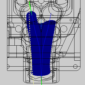
In the Area group, update the Machine to selection to Max. from bottom.
-
Click Compute.
In the images below you can see how this forces the toolpath further up the ports. 
Step 5) Simulation
-
To view the program, in the Quick access menu of the CAM Tree, click
Simulation. -
Click Play to view the operations in simulation.

-
To close simulation, in the
Exit Simulation. -
In the File menu, click Save.
Part 7) Recreating the Bottom features
Step 1) Copy, Paste, and place the features
-
In the Bottom > Rough group folder:
-
Right-click Rough Left Both Mid and select Copy.
For this step, and the remaining steps, we will not be copying with geometry. -
Right-click Machine Setup - 1 and select Paste.
-
Drag and drop the feature into the Top group folder.
-
Drag and drop the feature into the Rough group folder.
-
Right-click Rough Right Top Max and select Copy.
-
Right-click Machine Setup - 1 and select Paste.
-
Drag and drop the feature into the Top group folder.
-
Drag and drop the feature into the Rough group folder.
-
-
Repeat these steps for the features in the Bottom > Finish group folder, placing them in the Top > Finish group folder.
Step 2) Assigning geometry
-
For the two features in the Rough group folder, right-click Machine Surface/Mesh, select Re/Select, and pick all port surfaces.
These roughing features should include the additional surface between the two ports.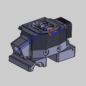
-
For the two features in the Finish group folder, right-click Machine Surface/Mesh, select Re/Select, and pick all port surfaces.
These finishing features should exclude the additional surface between the two ports. -
Assign Spine geometry for all features.

Left port spine.
Right port spine. -
Assign Gouge Check Surfaces for all features.
-
Compute each of the features.
Step 3) Simulate the end result
-
To view the program, in the Quick access menu of the CAM Tree, click
Simulation. -
Click Play to view the operations in simulation.
-
Run a deviation report to ensure the part is completed properly.
-
To close simulation, in the
Exit Simulation. -
In the File menu, click Save.
That concludes this example.