How to Use Edit Toolpath - Delete
Introduction
This example explains how to use the Delete option in the Edit Toolpath dialog box. The Delete command will allow you to select particular toolpath elements and adjust their position. The example provided will have you:
- Viewing the Stock and Toolpath
- Opening the Edit Toolpath Dialog Box
- Setting the Command Mode
- Selecting Toolpath Elements
- Setting the Parameters
- Executing the Action
- Viewing the Animation
- Exiting the Edit Toolpath Dialog
Example Part
The part file for this example is available for download at: http://bobcad.com/helpfiles. If you are connected to the Internet, you can click the link provided to download and save the Toolpath_Editor_Delete_Example SLDPRT.zip file. After extracting the zip file, you can open the file to follow along with this example. In the example file provided, the stock and Machine Setup are already defined for the part, and the toolpath to be adjusted has been applied.
Part 1) Viewing the Stock and Toolpath
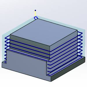
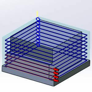
On our example part, we need to remove stock to a uniform depth on three of our four walls. The last wall only needs the top half of the stock removed. Take a moment to notice how the last four passes cut into the model. It is the last segments of the last four passes that we will need to remove.
-
In the

-
Take a moment to look at the existing stock compared to the existing toolpath.
-
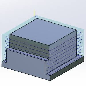
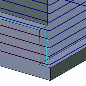
Rotate the part into a side view.
Notice the shorter depth of the wall on the left.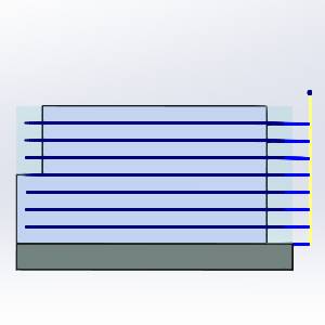
Part 2) Opening the Edit Toolpath Dialog Box
The Edit Toolpath function is only applied to individual operations, as such, the first step is always to right-click on the operation to be adjusted.
-
Right-click the
 Profile Rough operation
of the
Profile Rough operation
of the  Feature 2 Axis.
 -
Select Edit Toolpath.
The Edit Toolpath dialog appears.
Part 3) Setting the Command Mode
The Edit Toolpath dialog gives you access to multiple Commands. For this example, we will be utilizing the Delete Command.
-
Click the arrow on the Command list to view the list items.
-
Select the Delete option.
Part 4) Selecting Toolpath Elements
Now, we need to select the toolpath segments intersecting the solid model that we want to delete, and the lead-out moves they are connected to.
-
In the graphics area, select the toolpath elements highlighted in the image below.
With the toolpath segments selected, the preview is shown.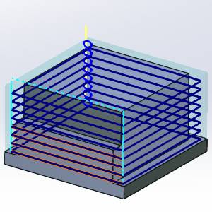
Part 5) Setting the Parameters
With the toolpath elements selected, we will need to set the Parameters to define how to link between the entities that still exist, since we are removing some of the toolpath. We can just leave the defaults and have the tool move to the rapid plane of the feature, but let's adjust it to stay a little lower and save some time. Be very cautions when making rapid moves occur around the part.
-
In the Parameters group, change the Retract option to Custom.
-
Enter -
The preview updates showing the new retract height.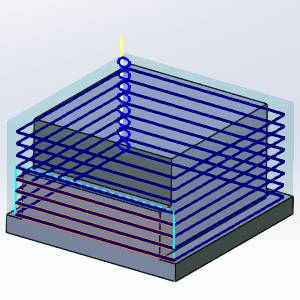
Note: When the Absolute or Incremental toggle is left at the default Absolute setting, the Rapid Plane value uses the Machine Setup as zero. As such, any height below the machine setup will be a negative value.
-
Select the Extension check box.
The Preview updates. Extension
 Extension

-
Enter 25 for the Extension value.
The Preview updates. Extension 50% Extension 25%
Part 6) Executing the Action
To move beyond the preview, and before clicking OK to finalize and exit, it is a good idea to Execute the current settings. Although clicking OK will Execute and exit simultaneously, using Execute will allow you to use Animation to verify the results and Undo the executed command if and adjustments necessary.
-
Click Execute.
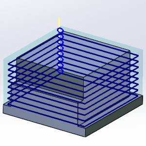
The toolpath elements update to show the effect of our edits.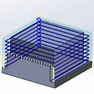
Part 7) Viewing the Animation
The Animation is an excellent way to double check the edits we have made to our toolpath elements. If any issues are noticed in the animation, we can easily undo our edits and make the necessary adjustments.
-
Select the check box for Animation.
The tool appears in the graphics area at the start of our toolpath. -
Use the Animation controls to play through the animation.
Part 8) Exiting the Edit Toolpath Dialog
Once the Animation has been viewed to ensure no further edits are needed, click OK to finalize and exit the Edit Toolpath Dialog. If you need to change the toolpath to its original state after clicking OK, recompute the operation.
-
Click OK.
The Edit Toolpath Dialog closes.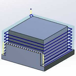
Important: Once the toolpath of an operation has been edited, the operation will be locked. In the CAM Tree, to the left of the operation name, which will be shown in red font, you will notice a lock icon:  . This ensures the toolpath can not be accidentally recalculated. To return the toolpath to its original state, or to update the operation with the wizard, and recalculate the toolpath, you must first right-click the operation and select Lock/Unlock Operation. The toolpath can then be recalculated to undo the edits that have been made to it with the Edit Toolpath dialog.
This concludes this example.