How to Use Edit Toolpath - Edit Tool Axis
Introduction
This example explains how to use the Edit Tool Axis option in the Edit Toolpath dialog box. The Edit Tool Axis command mode will allow you to adjust the axis of the tool on existing toolpath elements. The example provided will have you:
- Backplotting the Operation
- Opening the Edit Toolpath Dialog Box
- Setting the Command Mode
- Selecting Toolpath Elements
- Adjusting the Parameters
- Executing the Action
- Viewing the Animation
- Exiting the Edit Toolpath Dialog
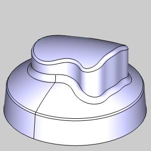
Example Part
The part file for this example is available for download at: http://bobcad.com/helpfiles.
If you are connected to the Internet, you can click the link provided
to download and save the Toolpath_Editor_ToolAxis_Example
Part 1) Backplotting the Operation
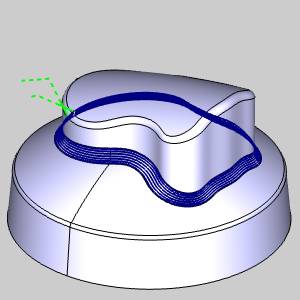
On our example part, we have created an Morph between 2 curves toolpath. In this case, while the toolpath on the main fillet is good, the tilt of the tool could use a little adjustment in particular areas. We will use the Backplot feature to get a preview of the tool movement and tilt.
-
In the CAM Tree, right-click the
 Multiaxis operation of the
 Feature Multiaxis.
-
Select Backplot.
-
Press
 Play to begin backplotting
the operation.
Play to begin backplotting
the operation. -
Adjust the Speed, Progress sliders, and the view in the graphics area as necessary.
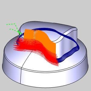
Take a moment to analyze the tool axis as it moves around the part, paying special attention to the area in the images below.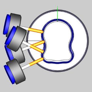
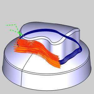
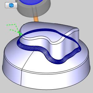
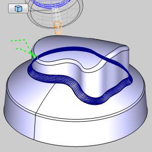
You can see, in the indented area on the side of the part, the axis of the tool crosses over itself. In this example, we will edit the area seen in the above image and have the tool axis, instead, move smoothly between the two tool axes seen in the images below.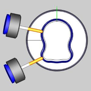
Part 2) Opening the Edit Toolpath Dialog Box
The Edit Toolpath function is only applied to individual operations, as such, the first step is always to right-click on the operation to be adjusted.
-
Right-click the
Multiaxis operation of the Feature Multiaxis.
-
Select Edit Toolpath.
The Edit Toolpath dialog appears.
Part 3) Setting the Command Mode
The Edit Toolpath dialog gives you access to eight different Command Modes. For this example, we will be utilizing the Replace Command Mode.
-
Click the arrow on the Command Mode list to view the list items.
-
Select the Edit Tool Axis option.
-
By default, the Preview check box is already selected. Leave this check box selected, as it will allow us to see a preview of the executable result, once our Selected Toolpath Elements have been confirmed.
Part 4) Selecting Toolpath Elements
Select the toolpath to be edited.
-
-
Select the
 Polygon
Pick option below the Selected Toolpath Elements list.
Polygon
Pick option below the Selected Toolpath Elements list. -
Select four points, as seen in the image below, to create a polygon around the area we intend to affect.
-
Right-click and select OK to confirm the selection of our toolpath elements.
The executable preview displays.
Part 5) Adjusting the Parameters
With the toolpath elements selected, we will need to set the Parameters to define the tool axis of the toolpath elements.
-
In the Parameters group, click the Direction Interpolation radio button.
The executable preview displays.
Part 6) Executing the Action
To move beyond the preview, and before clicking OK to finalize and exit, it is a good idea to Execute the current settings. Although clicking OK will Execute and exit simultaneously, using Execute will allow you to use Animation to verify the results and Undo the executed command if and adjustments necessary.
-
Click Execute.
Part 7) Viewing the Animation
The Animation is an excellent way to double check the edits we have made to our toolpath elements. If any issues are noticed in the animation, we can easily undo our edits and make the necessary adjustments.
-
Select the check box for Animation.
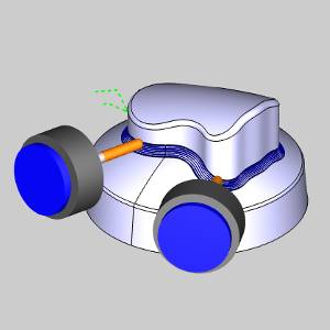
The tool appears in the graphics area at the start of our toolpath. -
Use the Animation controls to play through the animation. With either the
 (Solid),
  (Transparent), or
  (Wireframe)
view.
(Wireframe)
view.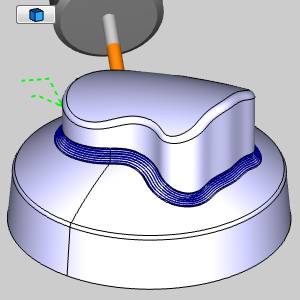
Notice the tool axis has been updated on one side of the part.
Part 8) Exiting the Edit Toolpath Dialog
Once the Animation has been viewed to ensure no further edits are needed, click OK to finalize and exit the Edit Toolpath Dialog. If you need to change the toolpath to its original state after clicking OK, recompute the operation.
-
Click OK.
The Edit Toolpath Dialog closes.
This concludes this example.