How to Use Edit Toolpath - Trim and Relink
Introduction
This example explains how to use the Trim and Relink option in the Edit Toolpath dialog box. The example provided will have you:
- Viewing the Stock and Toolpath
- Opening the Edit Toolpath Dialog Box
- Setting the Command Mode
- Positioning Part for Selecting Toolpath Elements
- Selecting Toolpath Elements
- Setting the Trim Boundary and Usage
- Adjusting the Link Options
- Executing the Action
- Viewing the Animation
- Exiting the Edit Toolpath Dialog
Example Part
The part file for this example is available for download at: http://bobcad.com/helpfiles.
If you are connected to the Internet, you can click the link provided
to download and save the Toolpath_Editor_TnR_Example
Part 1) Viewing the Stock and Toolpath
On our example part, we have used a
-
In the CAM Tree, click
 Stock
to view the assigned stock.
Stock
to view the assigned stock.
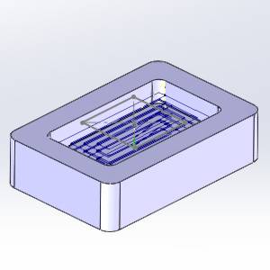
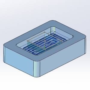
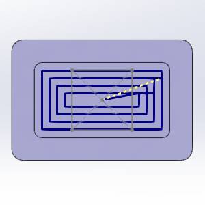
Take a moment to look at the existing stock compared to the existing toolpath to see what we intend to accomplish. -
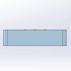
Rotate the part into a side view.
-
 TrimAndRelinkPart, and select
  Hide
Hide
The model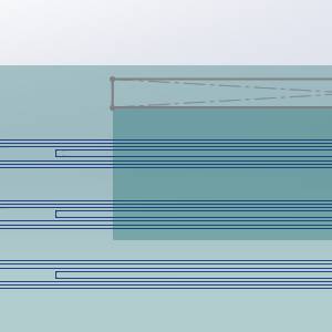
-
Zoom into the pocket.
Notice the final depth of the pocketing toolpath is not affected by the cavity in our stock. As, such, the first two depths of the pocket are the only ones that will need to be trimmed. -
TrimAndRelinkPart, and select Show
The model
Part 2) Opening the Edit Toolpath Dialog Box
The Edit Toolpath function is only applied to individual operations, as such, the first step is always to right-click on the operation to be adjusted.
-
Right-click the Pocket operation of the Feature 2 Axis.
-
Select Edit Toolpath.
The Edit Toolpath dialog appears.
Part 3) Setting the Command Mode
The Edit Toolpath dialog gives you access to eight different Command Modes. For this example, we will be utilizing the Trim and Relink Command Mode.
-
Click the arrow on the Command Mode list to view the list items.
-
Select the Trim and Relink option.
-
By default, the Preview check box is already selected. Leave this check box selected, as it will allow us to see a preview of the executable result, once our Trim Boundary has been confirmed.
Part 4) Positioning Part for Selecting Toolpath Elements
In this case, we are only trying to trim the first two depths of our pocketing toolpath. Because of this, a simple window selection from a top, or side view, will not be ideal. We will rotate the part slightly from a top view to allow us to select each toolpath element individually.
-
Put the part into a top view.
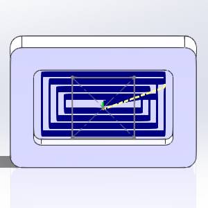
-
Rotate the part slightly to acquire a view as seen in the image above.
Part 5) Selecting Toolpath Elements
Select the toolpath to be edited.
-
In the graphics area, select the toolpath shown in the images below.
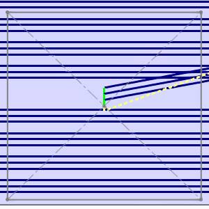
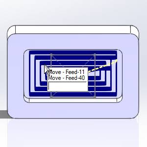
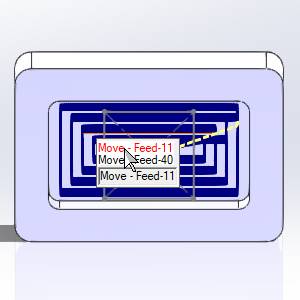
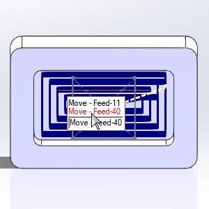
In the close up image below, notice we are only selecting toolpath elements from the first two depth passes. Although we could also select the first moves of the first and second layers, we leave them out for this example.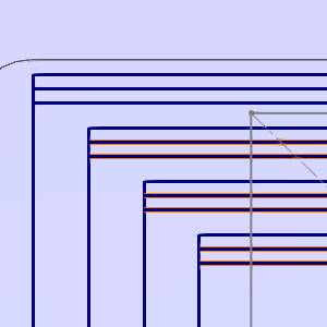
Note: When
toolpath elements are close enough together, attempting to select one
may cause a dialog to appear. This dialog will allow you to select, from
the dialog list, the intended toolpath element
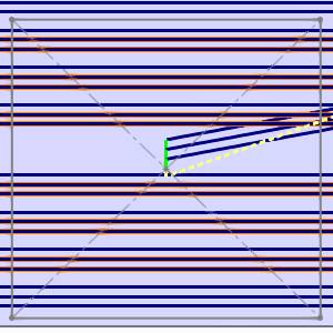
Part 6) Setting the Trim Boundary and Usage
With the toolpath elements selected, we will need to set the Trim Boundary to define which portion of the selected toolpath elements need to be trimmed.
-
In the Trim Boundary group, next to Usage, select the Along Z option.
This will ensure that selected toolpath elements are not left untrimmed due to our current view. -
In the Trim Boundary group, select the
 (Click or Drag Window Pick)
option.
(Click or Drag Window Pick)
option. -
In the graphics area
-
With the Trim Boundary selected, right-click and select OK to confirm selection.
The preview shows the executable result.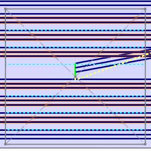
Tip: If all of the toolpath in the Trim Boundary area is to be trimmed, selecting toolpath elements is not necessary, as the Trim Boundary will automatically grab the toolpath elements within it. In this case, that was not possible, as we did not want the last depth pass to be trimmed.
Part 7) Adjusting the Link Options
Now that we have decided what toolpath elements to trim and where to trim them, we have to set the linking options. In this case, we will set the link type to a direct rapid move and adjust the extension value.
-
Set the Extension value to 60.
This will give us allowance for our tool radius, so the tool does not rapid into the stock. -
Remove focus from the Extension text field, by pressing Tab or clicking in another field
The preview updates to show the executable results of the current settings.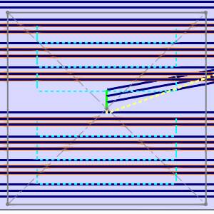
-
Set the Link option to Direct Rapid.
Tip: When using Direct Rapid, or Direct Feed, adjust the Extension option prior to the Link option. This allows you to see the resulting preview easier.
Part 8) Executing the Action
To move beyond the preview, and before clicking OK to finalize and exit, it is a good idea to Execute the current settings. Although clicking OK will Execute and exit simultaneously, using Execute will allow you to use Animation to verify the results and Undo the executed command if and adjustments necessary.
-
Click Execute.
The toolpath elements update to show the effect of our edits.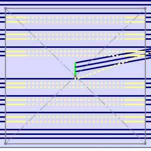
Part 9) Viewing the Animation
The Animation is an excellent way to double check the edits we have made to our toolpath elements. If any issues are noticed in the animation, we can easily undo our edits and make the necessary adjustments.
-
Select the check box for Animation.
The tool appears in the graphics area at the start of our toolpath. -
Use the Animation controls to play through the animation. With either the
 (Solid),
  (Transparent), or
  (Wireframe)
view.
(Wireframe)
view.
Part 10) Exiting the Edit Toolpath Dialog
Once the Animation has been viewed to ensure no further edits are needed, click OK to finalize and exit the Edit Toolpath Dialog. If you need to change the toolpath to its original state after clicking OK, recompute the operation.
-
Click OK.
The Edit Toolpath Dialog closes.
Important: Once the toolpath of an operation has been edited, the operation will be locked. In the CAM Tree, to the left of the operation name, which will be shown in red font, you will notice a lock icon:  . This ensures the toolpath can not be accidentally recalculated. To return the toolpath to its original state, or to update the operation with the wizard, and recalculate the toolpath, you must first right-click the operation and select Lock/Unlock Operation. The toolpath can then be recalculated to undo the edits that have been made to it with the Edit Toolpath dialog.
This concludes this example.