How to Vectorize Images
Introduction
This topic explains how to vectorize an image using BobART. Vectorization is the process of converting raster images into vector (sketch) geometry based on the color of each pixel contained in the image. The multi-color strategy and the black and white strategy are examined as well as the various workflow methods. There are two main methods to vectorizing images. For many images, only a single vectorization is needed to get the desired geometry. For very detailed color images, you may want to vectorize an image multiple times. The best method to use is a personal preference and depends on the task and image. This tutorial explains both methods and many helpful tips.
Example File
The part file for this tutorial is available for download at: http://www.bobcad.com/helpfiles. If you are connected to the Internet, you can click the link provided to download and save the Image Vectorization Example 1.SLDPRT zip file. After downloading the zip file, extract the files on your system in a place that is easy to remember. You can then open the file to use with this tutorial.
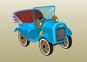
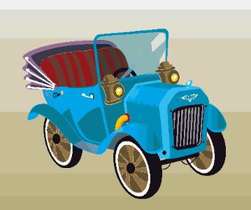
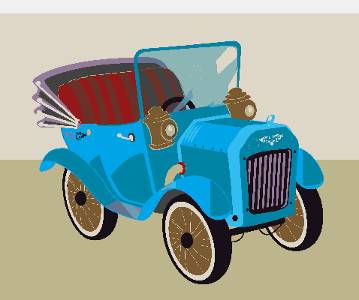
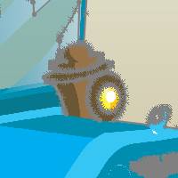
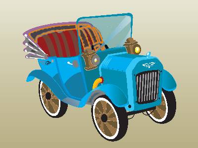
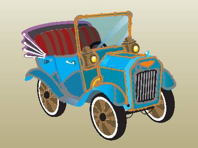
In this example, a color image of a car is used to create vector geometry.
This tutorials explains the following BobART functionality:
-
Loading an image using the BobART Manager
-
Selecting the image location
-
Hiding and showing images
-
Moving and scaling images
-
Using the Raster to Vector dialog box to vectorize an image
-
-
The 2-level black and white strategy
-
The multi-color strategy
-
-
Using Remove Chains Less Than
-
Editing the vectorization parameters
-
Exploring workflow methods and many helpful tips
Part 1) Open the Example File
-
In the File menu, click Open
-
In the Open dialog box, select the folder in which you saved the example files.
-
Select Image Vectorization Example 1.SLDPRT, and click Open.
The file is opened (the graphics area is empty). -
In the Manager Pane, click the
 BobART tab.
Part 2) Load the Image and Select the Image Location
-
In the BobART tree, right-click
 Images, and click Load
Image.
Images, and click Load
Image.
The Selection Manager displays for you to define the image location and orientation. You can select a plane, a planar face, or a surface edge. If you do not make a selection, the Front plane of the SolidWorks world coordinate system is automatically assigned. -
Select the FrontPlane from the Feature Manager design tree and click
 .
.
Note: We are selecting the Front Plane, so the vectorization result is placed in a 2Dsketch. If we didn't make a selection, the vectorization result would be placed in a 3Dsketch. (Either way the resulting geometry is the same, but working with the sketch feature in SolidWorks is slightly different.)
-
In the Open dialog box, select the folder in which you saved the example files.
-
At the bottom of the dialog box next to Files of Type, click the arrow, and select Windows Bitmap (.bmp) or All Files.
-
Select Old Car.bmp, and click Open.
The image loads and displays in the graphics area. You can press the F key to activate Zoom to Fit and view the entire image.
Notice the ![]() Image-Old Car vectorization feature
is added to the BobART tree under
Image-Old Car vectorization feature
is added to the BobART tree under ![]() Images. BobCAM also creates a sketch feature in the Feature Manager design
tree that contains the image (Sketch Picture).
Images. BobCAM also creates a sketch feature in the Feature Manager design
tree that contains the image (Sketch Picture).
Part 3) Hiding and Showing the Image
When vectorizing images, you can hide and show the image in order to view and work with the geometry that is created.
-
In the BobART tree, right-click
 Image-Old Car, and click Blank/Unblank.
The image is hidden. This method is used to hide or show a single image. -
Repeat step 1 to show the image again.
-
You can right-click Images and click Blank/Unblank All to hide and show all images that are loaded using the BobART Manager.
For this example, you can use either method to hide and show the image, because we only have a single image. For the remainder of this tutorial, when you are instructed to hide or show the image, use either method.
Part 4) Moving and Scaling the Image
For this example, we are simply vectorizing an image without using other geometry, so we can focus on the process of vectorizing the image. You may want to move or scale an image in order to use the resulting geometry with an existing model. This section shows you how to do so. You can use these steps before or after vectorizing an image, depending on how you prefer to work.
-
Right-click
Image-Old
Car, and click Change Origin.
The Sketch Picture properties display in the Property Manager tab. Note that you can accomplish the same task by double-clicking the image in the graphics area or any other SolidWorks method for modifying an image. -
You can drag the image to a new location, and you can drag the handles to change the image size. For this example, we modify the parameters using data entry.
-
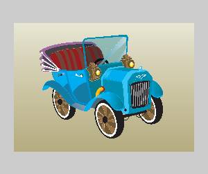
In the Property Manager under Properties, change the Width parameter to 8.00 and click
.
When we vectorize the image, BobCAM automatically uses the new image size.
Tip: When modifying the image this way, any previous vectorization result remains in the previous location. To update the results to the new location, you can simply open the Raster to Vector dialog box and click OK. Alternatively, you can use any standard SolidWorks functionality to move or modify the vectorized geometry. Any vectorization performed after moving the geometry, automatically uses the new location.
Part 5) Using the Raster to Vector Dialog Box
The 2 Level Black and White Strategy
This section explains how the Raster to Vector dialog box is used to create and modify the vectorized geometry. We start by experimenting with the 2 Level Black and White strategy, as it is a viable option for vectorizing color images or black and white images. The strategy simply determines how the image is analyzed in order to create geometry.
-
In the BobART tree, right-click
Image-Old Car, and click Vectorize.
The Raster to Vector dialog box displays. -
Under Vectorize Strategy, notice the 2 Level (Black/White) Strategy is selected by default.
-
In the Threshold Value box, select the text, and type 40.
Select the text again, and type 60.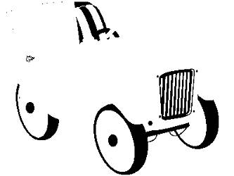
Notice the preview of the image updates each time that you change the value.
You can also click and drag the Threshold Value slider, in small increments, and release (to accomplish the same task).
Change the Threshold Value to 174.
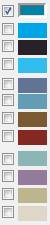
Click OK to vectorize the image and create a sketch feature. -
Hide the image to view the geometry. (Note that when hiding the image, a red X displays next to the image icon in the BobART tree.)
The resulting geometry is contained in a sketch feature that BobCAM automatically adds to the SolidWorks Feature Manager design tree. It is important to understand that when you edit the Vectorization parameters in the Raster to Vector dialog box, the previous result is replaced. (A new sketch feature is not automatically created for each vectorization.) This allows you to experiment with the vectorization result without creating excessive features or geometry. -
Next to
Image-Old
Car, click  to expand the tree item.
To edit the parameters, right-click Vectorization,
and click Edit. This item
is added to the BobART tree after the first vectorization.
Vectorization,
and click Edit. This item
is added to the BobART tree after the first vectorization.
(You can also right-click Image-Old Car, and click Vectorize.) -
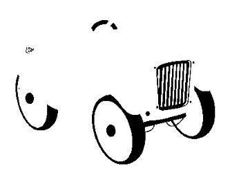
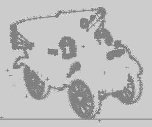
Change the Threshold Value to 111 and click OK to update the vectorization result.
Notice that the geometry from the first vectorization is removed and replaced with new geometry (using the same sketch feature).
You can zoom in to view the sketch geometry and notice that a great amount of detail is already available with the geometry created using just the 2 Level Black and White strategy. At this point, we could start editing the geometry to use for other features, but instead we begin using the multi-color strategy.
The Multi-Color Strategy
In this section we begin using the multi-color strategy to vectorize the image and begin exploring the various workflow options for creating and saving geometry.
-
Right-click
Vectorization,
and click Edit. -
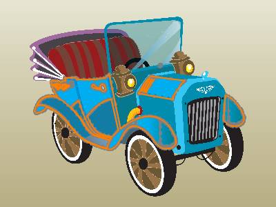
Under Vectorize Strategy, select Multi-Color Strategy.
The multi-color strategy defaults the number of colors to 64, which allows you to target very specific colors or color ranges in the image in order to be more precise with the vectorization results. Experimentation with the number of colors is an important aspect of learning to vectorize images in an efficient manner. -
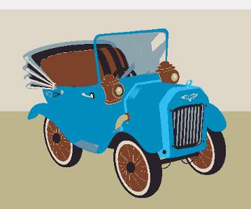
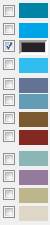
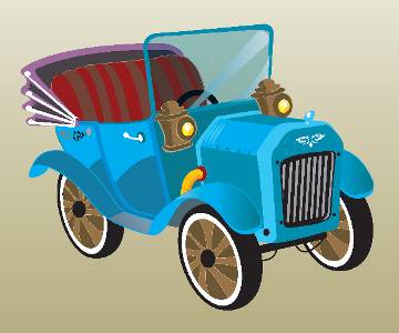
Next to # of Colors, click the down arrow and select 32. Notice the change in the preview. For example, the gradient of the image background is reduced from 6 unique colors to 5, and the yellow and orange colors are removed from the head lights and the exhaust.
When you change the number of colors, the image is actually reduced to the selected number of colors, and the color boxes update under Colors to be Vectorized.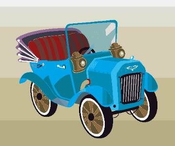
-
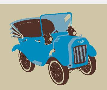
Continue reducing the # of Colors (for example to 16, 8, and 4), and observe the change in the preview.
-
Change the # of Colors to 24 and click Check All to automatically select the check box of all colors.
-
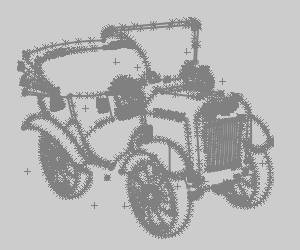
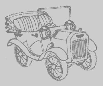
Click OK to vectorize the image.
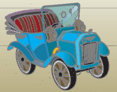
The image is processed using all 24 colors to create the vectorized geometry. Notice the horizontal lines. This is a result of the gradient in the background of the image. The current settings separated the gradient into three unique colors.
Although it is not the method used for this tutorial, you could decide that you are now done with the vectorization and simply edit the geometry. Depending on what you want to achieve, this may not be the most efficient method to use. When using this method, you are vectorizing many adjacent colors, which results in a large amount of entities. Regardless of how you choose to work, we explore another important parameter next, Remove Chains Less Than.
Remove Chains Less Than
The Remove Chains Less Than parameter is very important when vectorizing images, as it helps you to remove unnecessary geometry that may be created from the gradients in an image.
-
Show the image, and zoom-in closely to different areas of the image and notice the geometry as compared to the selected colors (gradients). For example, the grill on the front of the car or the wheels are a great place to view how the geometry is created based on the colors.
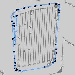
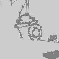
The following image shows the colors of the front grill zoomed in closely with the geometry hidden from view. You can see that there are actually three colors that make the vertical black and gray stripes.
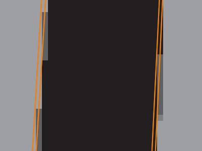
Because we have vectorized all 24 colors, the software created geometry for each color. The first point here is that you may not want to vectorize adjacent colors, as it results in what appears as duplicate geometry, although it isn't. It may be better to vectorize only one of the colors. The second point is that the darker gray color results in very small entities that are most likely not needed. The geometry from our vectorization is shown next highlighted to make it easier to view.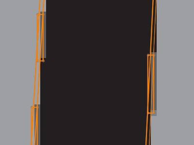
You can see the small rectangles are not needed, so now we use the Remove Chains Less Than parameters to remove them. -
Right-click Vectorization, and click Edit.
-
Under Vectorization Parameters, change the Remove Chains Less Than value to 100 (pixels), and click OK.
You can see that the small groups of entities are now removed from the result. You can experiment with the Remove Chains Less Than value to make the vectorization result more efficient. Next we explore more ways to be efficient with vectorization.
Tip: Be sure to reduce the Remove Chains Less Than value (if needed) when moving on to vectorize different areas of the image.
Part 6) Targeting Specific Color Ranges
When vectorizing very detailed images or when using many colors, it is often helpful to only vectorize a few colors at a time. This also helps to eliminate creating similar (almost duplicate) entities, when vectorizing adjacent colors as shown previously.
Target the Grill and Create a New Sketch
-
Right-click Vectorization, and click Edit.
-
Reduce the # of colors to 3, and click the Uncheck All button.
-
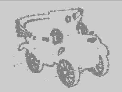
Click to select only the top or first check box (blue color), and click OK.
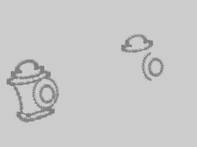
Hide the image to view only the resulting geometry.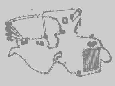
When using this method of targeting specific colors or areas of the image, you copy and paste the desired geometry to a new sketch in order to keep it, so that it is not replaced with the next vectorization. -
Zoom-in to view the front of the car (the grill), and notice how clean the result is compared to the earlier vectorization result. There are no unwanted small entities or duplicates.
For the next step of copying the geometry, you can either simply select the entities you want to keep, or you can edit the sketch feature to enable some more selection options. For this example, we use the Select Chain option. -
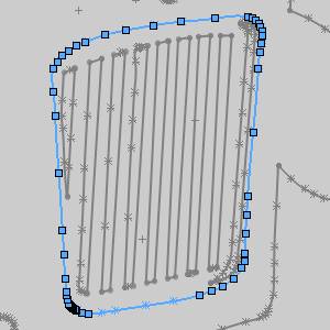
Click to select the outer profile of the grill.
-
Now hold Shift, right-click the next profile, and click Select Chain.
Tip: The SolidWorks Select Chain option is a great way to obtain clean geometry from the vectorization result, whether open or closed chains, especially when vectorizing adjacent colors.
Repeat this process, holding Shift
and using Select Chain to select
all profiles of the grill. When they are all selected press Ctrl+C
to copy the geometry.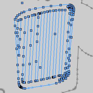
-
In the Feature Manager design tree, click to select Front Plane, and press Ctrl+V to paste the selected geometry to a new sketch feature (Sketch2). You can rename the feature to Grill to make it easier to remember later.
Tip: When copying and pasting geometry to keep, it is helpful to hide the new feature from view until you are finished vectorizing the image. (Right-click the feature and click the Hide icon.)
Target the Outer Profile
We could have also copied the profile of the car using the previous vectorization result, but it is not the entire outer profile. Next we get the outer profile of the entire car using a similar process.
-
Right-click Vectorization, and click Edit.
-
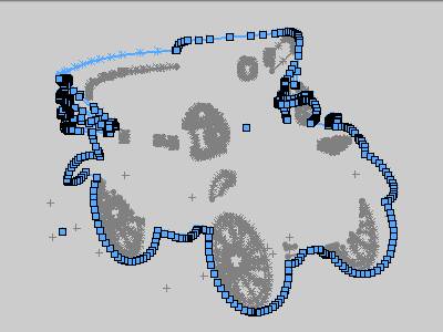
Click to clear the top check box (blue color), and select the bottom or third check box (tan color).
-
Click OK to update the vectorization.
-
Right-click the outer profile, and click Select Chain. (Be sure to right-click a line, arc, or spline, not a point, as the Select Chain option does not display when right-clicking a point.)
-
Copy the geometry and paste it on the Front Plane as explained earlier.
-
Rename the feature to Outer Profile and hide it from view.
Note that we used only single colors to express the point of targeting specific areas of the image and to show how much you can accomplish this way. It is not always necessary to simplify the process this much, as you can vectorize more than one color at the same time.
Part 7) Continue Vectorizing the Image
The process explained thus far is all that is needed to accurately and efficiently vectorize detailed images. Again, experimentation is the best way to define your own workflow. The following sections provide an overview creating all the geometry needed from the car.
Before editing the vectorization parameters, we also copy geometry from the headlights. A helpful note here is to show the image to compare the resulting geometry. We do this because it appears as though one of the headlights is missing some geometry.
After showing the image to compare, we can see that there is not any geometry missing from the headlight.
Tip: Hiding and showing the image is an important part of analyzing the vectorization result. Be sure to use this functionality as needed to confirm and compare the resulting geometry.
The following geometry is copied and pasted to a new sketch feature named Headlights.
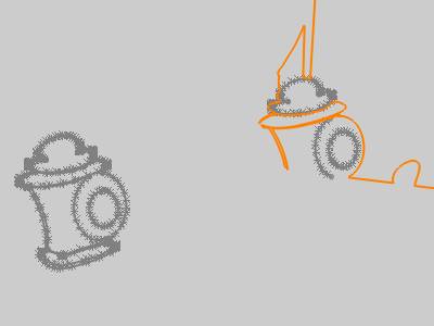
Notice that only some of the geometry from the right side is copied. The portion that was not copied already exists on the Outer Profile sketch feature as shown next (the outer profile feature is highlighted in orange). Be sure to hide and show (or highlight) each new sketch that you create in order to avoid copying duplicate geometry. Note that the highlighting shown is done simply by pointing to the sketch feature in the Feature Manager design tree without clicking.
By setting the number of colors to 12, and selecting the third color from the top, the following geometry is copied and pasted to a sketch feature named Seat.
Continuing with 12 colors, using only the second color results in the following geometry, which is copied to a new sketch (Body) feature as shown next. Remember that the vectorization result contained more geometry than what was copied.
Note that both of the previous colors could be vectorized at the same time. They are separated in this tutorial only to show which geometry is copied from each color.
Another color is selected using the 12 number of colors setting to copy more of the body geometry. Note that this time, the geometry is copied to the same Body sketch feature created previously and moved to the correct location, instead of making a new sketch feature.
The process of modifying the number of colors, picking a target area, and vectorizing the image using a small number (and ideally non-adjacent) colors at the same time is continued until all desired geometry is created. This geometry can then be used to create other SolidWorks features, or it can be used directly with BobCAM for machining features.
Final Notes
Remove Arcs or Splines
If you want to create the vector geometry using only line segments,
clear the ![]() With Arcs check box
as well as the
With Arcs check box
as well as the ![]() With Splines check
box in the Raster to Vector dialog box. You can use either of these options
to force the results to use only certain entity types, such as lines and
arc or lines and splines.
With Splines check
box in the Raster to Vector dialog box. You can use either of these options
to force the results to use only certain entity types, such as lines and
arc or lines and splines.
Editing Resulting Sketches - Automatic Solve
When vectorizing images, the software may create a very large number of entities in the resulting sketch feature, depending on the settings you define. When editing the sketch feature, SolidWorks may automatically disable the Automatic Solve option due to the large sketch. When this happens you cannot drag entities to move them without turning on the Automatic Solve option. To turn the option back on, you must be editing a sketch. In the Tools menu, point to Sketch Settings and click Automatic Solve. (This option cannot be turned on or off when you are not editing a sketch.)
Open the Image for Reference
You may want to open the image file you are using outside of the software so you can reference it while working. This can be very helpful, especially when you have more than one monitor. This can help you save time and make it easy to compare the vectorization results to the original image.
Vectorize Parameters - Accuracy
The Accuracy parameter can be changed to create smoother or rougher contours.
Low Accuracy (0.10 pixels)

High Accuracy (0.90 pixels)

This concludes the tutorial.