BC Mill Turn Machines
Understanding Mill Turn Machines in BobCAM
This topic introduces you to the mill turn machines that are installed with the BobCAM software. These machines are used for all examples in the system and knowing how to program mill-turn jobs starts with understanding the correlation between your physical machine and the virtual machine in BobCAM.
Note: Mill Turn is synonymous with turn milling, multitasking, a lathe with live tooling, or a 3-5 axis lathe.
BC 1T1S
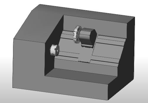
This machine is a common mill turn configuration with a single turret (tool-holding device) and a single spindle (work-holding device). This machine has 3-axis or XZC machining capabilities and a single submachine (work zone). The ability to mount live tooling to the turret is what separates this mill turn machine from a standard 2-axis lathe.
BC 1T2S
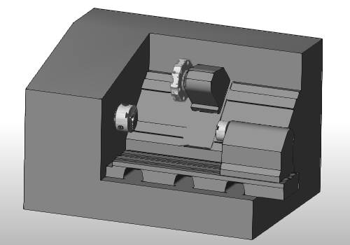
Another common mill turn configuration uses a single turret and two spindles. This machine has 3-axis or XZC machining capabilities and two submachines (work zones). This machine configuration is beneficial because it includes a subspindle (with linear travel), so you can transfer the part from the main spindle to the subspindle to perform work on the back side of the part, helping to reduce setup time.
BC 1T2S Y
Similar to the BC 1T2S, this machine uses a single turret, two spindles, and adds Y-axis machining capabilities that allow for more versatile milling that cannot be accomplished on machines without a Y-axis. This multiaxis machine has 4-axis or XYZC machining capabilities and two submachines (work zones).
BC 2T2S Y
This multiaxis mill turn configuration uses two turrets and two spindles and adds Y-axis machining capabilities to the upper turret only. This machine has 4-axis or XYZC machining capabilities and four submachines (work zones). This machine configuration is extremely versatile because you can mount tools to a second turret, and both turrets can work on either spindle.
BC 2T2S 5X
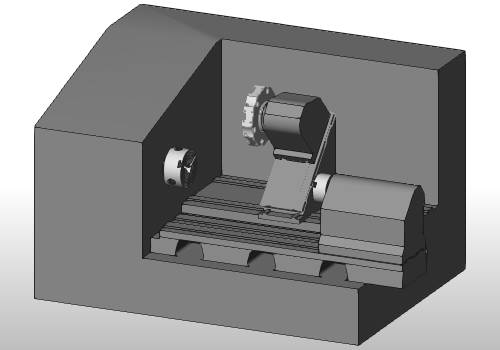
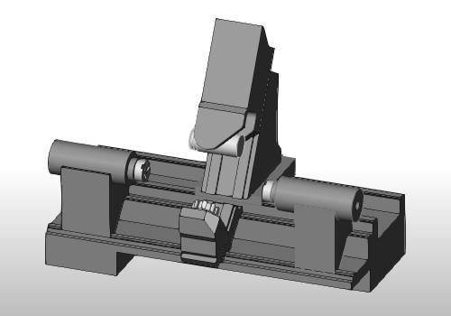
This multiaxis machine contains two tool holding devices, one turret and one milling spindle/head, and two spindles. This machine allows for 5-axis or XYZBC machining capabilities with the addition of the milling spindle. This machine configuration is highly desirable for its multiaxis capabilities and four submachines (work zones).
Building and Programming for Your Machine
You can absolutely use the BobCAM software to create your own virtual mill turn machine for the software, but most people contact the experts at BobCAM Technical Support to work through the machine setup process, as well as getting a post processor. Detailed information is included in the Help system, but the following are a few key points on how you should think about the virtual machine in BobCAM.
Machine Definition and the Virtual Machine Zero/Coordinate System
When creating or programming a mill turn machine, you must think about the machine zero and the direction of each axis in this coordinate system. The virtual machine zero is our primary reference in the software and all BC machines use the same location, the front face of the main spindle. For example, when setting the machining origin (work offset) in the software, it is in reference to the virtual machine zero. When setting up the machining origin (work offset) on the physical machine, the machine controller handles the machine zero location that is most likely not the same as the virtual machine zero.
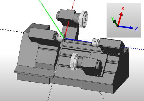
All geometry files are aligned to the virtual machine zero for the machine definition, and this is also our reference for creating tool adapters and when mounting adapters and tools to the machine devices in the tool crib.
Tip: The arrows of the coordinate system gnomon indicate the position direction of each axis. Notice that the Z-axis is the center line of rotation for the lathe spindles. This reference is also helpful when mounting tools in the tool crib.
Submachines
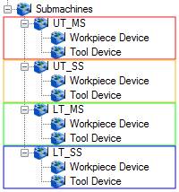
All mill turn machines have submachines, which are also known as work zones. Submachine is an important term that is used in programming mill turn in BobCAM. A submachine determines which machine devices are performing machining operations and it contains two machine devices: one workpiece device and one tool device.
|
Submachine Tree |
Submachines - Device Grouping |
|
|
|
Programming CAM Features
Although some machines contain more than one submachine, generally, all programming for mill turn jobs is done as though it is being programmed for the upper-left submachine (or the main spindle and upper turret). The point here is that you create one set of geometry to assign to machining operations regardless of which submachine is performing the work.
Turning
Turning profiles are drawn in the XZ plane of the machining origin (work offset) that you define in the Machine Setup.
Face Milling and Drilling
For face milling or drilling work (Z-axis), you program just as you would for any mill job, where the tool is parallel to the Z-axis of the machine setup (work offset).
Cross Milling and Drilling
For cross milling work (X-axis), you use index systems, wrapping groups, or the rotary feature, and for cross drilling work you use the cross drilling or multiaxis drilling types.
Y Axis Machining
No Y-axis
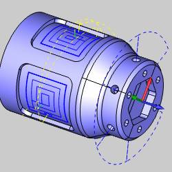
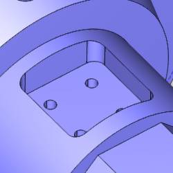
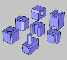
The pocket shown next can be machined without Y-axis machining capabilities.
All holes shown next also do not require Y-axis movement.
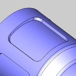
Y-axis Machining
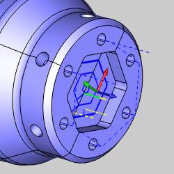
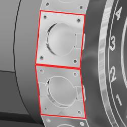
The pocket (and holes) shown next require Y-axis machining capabilities.
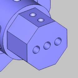
Tool Orientation Differences
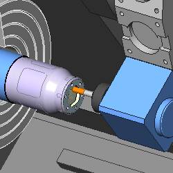
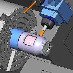
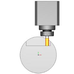
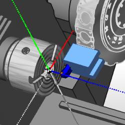
Machining flat areas, for example a hex on the front of the part as shown in the following images, generally can be achieved with or without Y-axis machining capabilities. The difference here is the tool orientation determines how these flat areas can be machined. On Y-axis machines, you can cut with the tool parallel to the X-axis so you are cutting with bottom of the tool. On machines without a Y-axis, however, the tool must be parallel to the Z-axis, so you are cutting with the side of the tool.
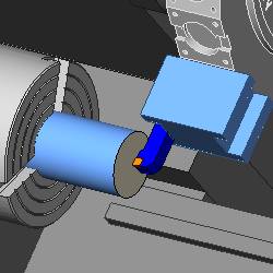
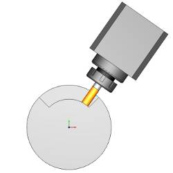
The following image shows machining flats on the front face that doesn't require Y-axis movement. (Machines with a Y-axis can also perform this type of machining, but can do it in two ways: fixed C-axis with XY movement or fixed Y-axis with XC movement.)
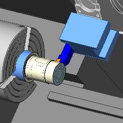
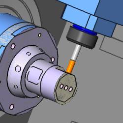
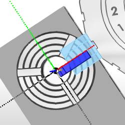
The next image shows another option for machining these flats that can only be accomplished with Y-axis capabilities.
Tool Devices and Adapters
There are a few key points to understand about mounting tools to the turrets of a mill turn machine. To create the most accurate simulation and provide for proper collision detection, you should create custom adapter geometry that is used to mount mill or lathe tools to turrets or milling spindles.
Custom Adapter Geometry
Understanding the alignment of the virtual machine helps to make custom adapter creation much easier. When creating custom adapter geometry, again we think about our virtual machine zero and the orientation of the adapter/tool when it is in the working position on the machine. As explained earlier, we can think about the upper-left submachine (main spindle and upper turret) when creating our adapters. The software then provides options for rotating and shifting the adapters in the event we need to use them in a different orientation. (Note that you can also create adapters for each orientation that is used on the machine, but this isn't necessary.)
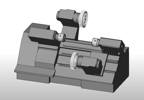
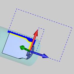
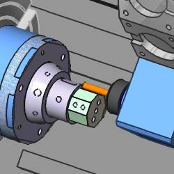
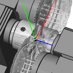
The next image shows the alignment of all machine devices to our virtual machine zero (as defined for the machine definition).
Turret Stations
Any turret may contain one or more mounting positions at each turret station (tool mounting location), which are also called substations. One main point to understand is that front (in the BobCAM software) refers to the substation that is closest to the main spindle.
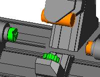
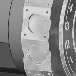
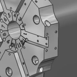
The following turret (from the 2T2SY machine) contains only side mounting substations at each turret station.
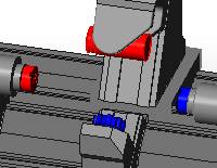
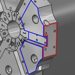
This image shows a turret with both front and side substations (note that only the odd numbered stations have a side mounting location). (Blue indicates the front mounting locations, and red indicates a side mounting location.)
Turret Substations and Adapter Mounting Locations
The goal when creating adapters is to define a reference point (mounting location) on the adapter that corresponds to the reference point at the turret substation. The turret of the virtual machine is defined with one reference point per substation. We create our adapter reference point to match the turret substation reference point.
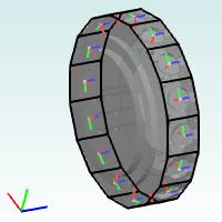
The following image shows all the substation reference points defined in the turret definition (note that there are side substations only on this turret). Notice the gnomon in the lower-left corner. This represents our virtual machine zero.
When creating adapters, again we only need to think about the substation/adapter orientation in the working position or zero degree location.

Creating Tool Adapters
To learn more about creating tool adapters, view the following topics: