How to Create a Corner Rounding Operation
Introduction
This topic explains the process of creating a Corner Rounding operation using the Mill 2 Axis Wizard. You learn how to properly select geometry, set the depth, and define the tool data to create the operation for the outer and inner profiles of the example part. You can apply the information in this example to any part (or just a rectangle).
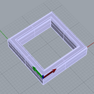
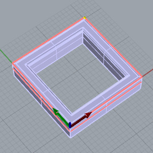
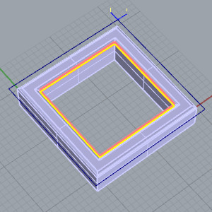
The following image shows the part used in this example with the machining origin set to the top of the part.
Example
Part 1) Load the Tool Crib and Create the Feature
After creating a Milling job and defining the stock geometry, use the following steps.
-
In the CAM Tree, right-click Milling Tools and click Tool Crib.
-
In Tool Crib, click Add From Tool Library.
-
On the left under Mill, click Corner Round.
-
Click to select the tool with the
-
In the Tool Crib, click OK.
-
In the CAM Tree, right-click Machine Setup, and click Mill 2 Axis.
Part 2) Select the Feature Geometry
-
Under Geometry Selection, click Select Geometry.
The FeatureGeometry Picking dialog appears with the focus on the Selected Geometry list to allow you to select geometry for the feature. -
You can select wireframe or surface edges for the operation.
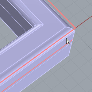
For this example, point to the outer surface edge at the bottom of the fillet.
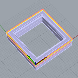
The feature preview appears. Note that you could also select the bottom surface edge of the part for this example, as long as you select the outer profile of the part.
The Z-level of the selected geometry is not extremely important for this example because the depth of the feature is set using the Top of Feature and the Total Depth.
Setting the Chain Start Point and Direction
-
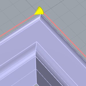
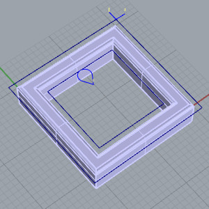
In the Profile Chains list, select Chain-1.
The Chain highlights in the graphics area and the start point and the direction of the chain are shown as an arrow.
-
Next to the Profile Chains list, click
 (Reverse Direction) to
reverse the direction of the chain.
(Reverse Direction) to
reverse the direction of the chain. 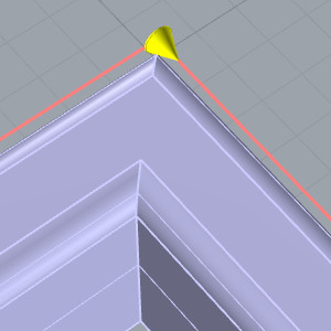
With the default setting of Left for the System Compensation, the clockwise motion on the outside of our part will create a Climb cut.
Defining the Total Depth of the Feature
Next we use the Pick Bottom list to update the Total Depth value for the feature.
-
Under the Feature Parameters, in the Total Depth group, click in the Pick Bottom list to give it focus.
-
Click on the bottom edge of the fillet on the model to set that as the total depth of the feature.
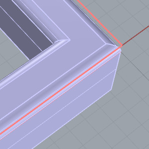
The Total Depth updates along with the preview. -
The Feature Geometry Picking dialog disappears and the Mill 2 Axis Wizard returns. -
Click Next>> to go to the Feature page.
Part 3) Define the Feature and Operation Parameters
-
In the Material Approach group, set the Rapid Plane and Feed Plane for the feature.
The Top of Feature was automatically set to 0.00 because the machining origin is placed at the top of the stock. The Total Depth was set in the Feature Geometry Picking dialog.
Tip: This feature contains only one operation: Corner Rounding. With this being the only operation, we set the Total Depth for the feature to be the depth needed for the Corner Rounding operation. To allow you to create other operations, such as pocketing or profiling operations, in the same feature, the depth of the Corner Rounding operation can differ from the overall Total Depth of the feature by setting it in the Parameters page of the Corner Rounding operation.
Click Next>> to go to the Machining Strategy.
Set the Machining Strategy, Posting Options and Tool Data
-
Click
 (Delete Operation) twice to delete both operations from the Current Operations list.
In the Available Operations list, select Corner Rounding, and click (Add Operation)
to add a single operation to the Current Operations list.
(Add Operation)
to add a single operation to the Current Operations list.
The Machining Strategy is defined.
Click Next>> twice to go to the Posting settings. (Skip the Tabs page.) -
Set the proper Work Offset # and click Next>> to go to the Tool settings.
-
In the Tool Data group, the proper tool data is already loaded from the tool in the Tool Crib that matched the operation type.
Note: When you preload tools in the Tool Crib and then type values into the available System Tool parameters (Diameter, Small Diameter, and Corner Radius), the proper tool data is automatically loaded when there is a matching tool, including the tool holder assignment, tool number, and feeds and speeds values.
To learn more about defining a Corner Rounding tool, view The Tool Page.
Click Next>> to go to the operation Patterns.
Define the Type of Compensation
-
In the Patterns settings, the Standard pattern and System Compensation Left are selected.
Note: Tool compensation for the Corner Rounding tool uses the Small Diameter of the tool.
Click Next>> twice to go to the operation Leads.
Define the Type of Compensation
-
In the Leads settings, a Parallel Lead-in is selected with a Length of
For the remaining operation parameters, the default Sharp Corners is used (and the Machine Sequence doesn't apply to a single contour).
To learn more about all operation parameters, view The Corner Rounding Operation. -
To create the feature, click Compute.
Part 4) Create the Second Feature
For this example part, there is also an internal feature that needs cut. Because we want to use a different lead type on the inside, a second feature is created. Note that this feature could also contain a Pocket operation and/or Profile operation in addition to the Corner Rounding operation. For this example, we only create the Corner Rounding operation.
-
In the CAM Tree, right-click the Feature 2 Axis and select Copy.
-
In the CAM Tree, right-click the Feature 2 Axis and select Paste.
A dialog appears asking Do you wish to load the Top of Feature and Depth values? -
This dialog gives us the opportunity to copy the feature while leaving the Top of Feature and Total Depth values at their usual default values. In this case we want to use the same Top of Feature and Total Depth values.
Click Yes.
Select the Feature Geometry
-
In the new Feature 2 Axis, right-click on Geometry and click Re/Select.
The FeatureGeometry Picking dialog appears with the focus on the Selected Geometry list to allow you to select geometry for the feature. -
The feature preview appears. Notice the Total Depth already has the proper value.
Since the System Compensation in our feature is already set to Left, our chain direction is also correct. -
The Feature Geometry Picking dialog disappears.
Set the Leads
-
Right-click on the new Feature 2 Axis and select Edit.
-
In the Tree on the left, click on Leads.
-
In the Lead-in group, select Blend.
The Lead-out updates automatically since the Same As Lead-in check box is selected. This causes the entry and exit to use the same location inside the part.
Part 5) Simulate the Program
-
In the quick access toolbar of the CAM Tree Manager, click
 Simulation.
To learn more, view Getting Started with Simulation.
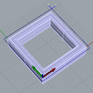
After simulating, the stock model appears as shown next.
-
To close the simulation window, click
 Exit Simulation.
Part 6) Post the Program
-
To post the code for the program, right-click
 Milling Job,
and click Post (or Post
and Save As).
Milling Job,
and click Post (or Post
and Save As).
The NC program (G-code) displays in the Posting tab of the Layer-UCS-Posting Manager.
This concludes the example.