Mill Turn Part Transfer Example
Introduction
The purpose of this document is to show an example of a successful part transfer and to detail the values which need to be updated when creating a part transfer of your own.
BC 1T 2S Mill Turn Machine
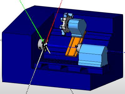
This example uses the BC 1T 2S Mill Turn machine.
BC 1T 2S Submachine Naming
The submachine naming used for the BC 1T 2S is as follows.
|
UT_MS = Upper Turret, Main Spindle |
UT_SS = Upper Turret, Sub Spindle |
|
|
Example Part
The following images show our example part. For this example, we machine the part using stock that is already cut to length. For this reason, we create our features as though the model is split into two halves: front and back. This allows us to machine the front half of the part on the main spindle before transferring the part to the sub spindle and machining the back half. This is important to understand as this determines how we set the needed values.
![]()
![]()
Machine Setups
For this example, all features are created using two machine setups: one for the front side and one for the back side of the part. The following images show the location and orientation of the machining origin (work offset) for each setup.
|
Machine Setup 1 (UT_MS) |
Machine Setup 2 (UT_SS) |
|
|
|
The Mill Turn job, stock, machine setups, and features are already defined in the part file provided for this example.
Example File Download
The BobCAD part file for this example is available for download at:
http://bobcad.com/helpfiles.
If you are connected to the Internet, you can click the link provided
to download and save the Mill Turn Part Transfer
This example highlights the following features of the BobCAD-CAM software:
- Work Offset Values:
- Z
- Subspindle Z
- Spindle Park Position
- MDI Part Transfer Values
Part 1) Update Work Offset Values: Machine Setup - 1
When simulating your machine, it is important to have the proper work offset values. In a Mill Turn job, whether you are working on the main spindle, or the subspindle, the machine setups are placed at the center of the appropriate spindle chuck face. The Work Offset values allow you to compensate for this by specifying the values to offset the position of the machine setup by. First we simulate to note the current state, and then alter the Work Offset values for the first Work Offset.
Simulate
- In the CAM Tree Manager, right-click Mill Turn Job, and select Simulation.
The Simulation launches. - Notice the stock, and associated toolpath, are all inside of the main spindle.
This is because of the default Work Offset Z value of zero lining our Machine Setup with the center of the chuck face.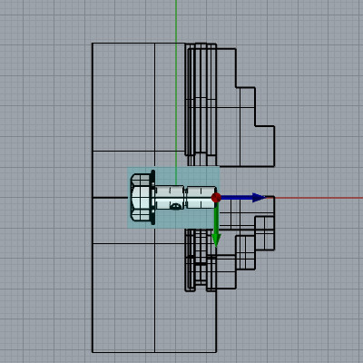
- Exit the simulation.
The simulation closes.
Edit the Work Offset Z value
- Right-click on Machine Setup - 1 and choose Edit.
The Machine Setup dialog opens in the Data Entry Manager. - At the bottom of the Machine Setup dialog, click Work Offset.
The Work Offset dialog opens. - Set the Z value to
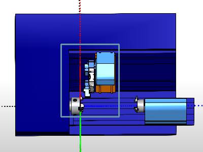
This positions the machine setup, and therefore the part and the stock, as shown in the image below.
This should give us sufficient material to hold on to, while exposing enough material to complete the work on the first setup without contacting the chuck jaws.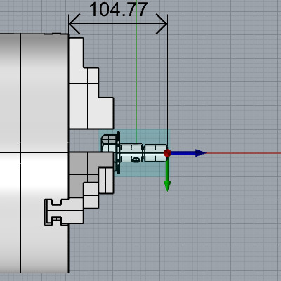
Tip: It can be helpful to draw a quick sketch of the jaws being used in the chuck to determine how far out to position the machine setup from the spindle chuck face. This is shown in the image below. To find out more about defining chucks and chuck jaws, see The Chuck Configuration Dialog topic.![]()
Edit the Work Offset Subspindle Z value
- In the Work Offset dialog update the Subspindle Z value to match the Z value of
- Click OK.
The Work Offset dialog closes.
Note: We will get into the reasons for the Subspindle Z value in part 4 of this example.
Part 2) Update Work Offset Values: Machine Setup - 2
With the Work Offset for the first setup updated, we now update the Work Offset values for the second setup.
Edit the Work Offset Z value
- When we exited the Work Offset dialog, the Machine Setup dialog remained open.
At the top of the dialog, click the drop down under Machine Setup, and select Machine Setup - 2. - At the bottom of the Machine Setup dialog, click Work Offset.
The Work Offset dialog opens. - Set the Z value to
Again, this specifies the distance the Machine Setup should be offset from the spindle chuck face.
| Work Offset value: 0.00 | Work Offset value: |
|
|
|
Edit the Work Offset Spindle Park Position value
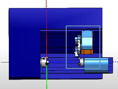
If, in the first step of this example, you played through the simulation, you may have noticed the work being done on the second setup was being done with the two spindle faces pressed against each other. This is because the Spindle Park Position was still set to zero. In the Spindle Park Position, specify a distance from the face of the main chuck, at which the work on the second spindle should be completed.
- Set the Spindle Park Position to
- Click OK.
The Work Offset dialog closes. - At the bottom of the Machine Setup dialog, click OK.
The Machine Setup dialog closes.
Part 3) Simulate
We now simulate to verify the correct positions in simulation.
- In the CAM Tree, right-click Mill Turn Job, and select Simulate.
The simulation launches.
Note: The following steps, regarding adjusting the visibility of various components in the simulation are not necessary, but can be helpful when visualizing the position of the stock in the chuck jaws. For information about this, and the simulation in general, see the Getting Started with Simulation topic.
- Using the Visibility group, in the Simulation tab, click Toolpath to hide the toolpath.
- Set the Stock to Transparent.
- Set the Workpiece to Show.
Notice the position of the part in the main spindle: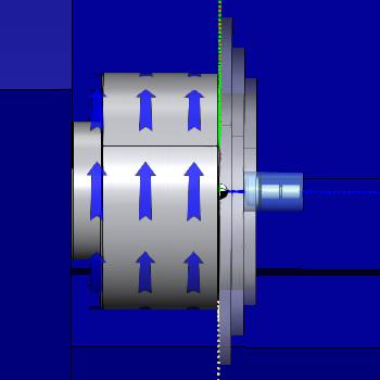
- In the Move List, click Op. 10: "Lathe Thread-60 DEG - LAY DOWN".
The simulation jumps to this operation. - Set the Simulation Run Speed slider to about 25%, (with 0% being all the way to the left).
- Click Run.
The Threading operation is completed, and the stock jumps to the subspindle.
Notice the stock position in the subspindle.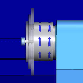
Note: You may also notice, the work being done is now well away from the main spindle. This is due to the value we used in the Spindle Park Position in the second machine setup.
- Click Stop when you are done viewing the simulation.
- Exit the simulation.
The simulation closes.
Part 4) Add the Part Transfer
In the last part, we noticed the part jumping from one spindle to the other. This occurred because we had no part transfer created. In this part, we create that transfer, and review the needed values.
Load the GenericPartTransfer
-
In Machine Setup - 1, right-click Feature Lathe Thread, and select Edit.
The Lathe Wizard launches.
-
In the tree on the left of the Lathe Wizard, click MDI.
The MDI page appears.
- Under the Task List, on the right, click
 (Load) in the Save/Load group.
The Open dialog appears. - Select GenericPartTransfer.bcmdi, and click Open.
The Load MDI Task dialog opens.
By default, Full Replace is already selected as the option. - Click OK.
GenericPartTransfer Values
When we loaded the GenericParTransfer, an expander icon appeared next to the After Operation task in the Task List group. This is where all the lines/commands controlling the part transfer can be found.
- Click the expander next to the After Operation task.
The lines become visible.
While each line can be tailored to your needs, the main items for viewing the movements in the simulation are:- Move Sub Spindle To Clearance.
This is designated as the rapid move toward, but still a safe distance from, the part. - Start Fast Feed Up To Part.
This is designated as a faster feed move to get closer to the pickup location. - Feed To Pickup Location.
This is designated as a slow feed move to the final pickup position. - Part Transfer.
This is what moves the part in the simulation, and the value should match the Feed To Pickup Location value.
- Move Sub Spindle To Clearance.
Adjusting the GenericPartTransfer Values
The values used in the commands of the part transfer are based on the values assigned to the subspindle in the Work Offset dialog of the first machine setup. By setting our Subspindle Z value to match that of the Z value, as we did, we ensure that a zero value will place the face of the subspindle directly on the first machine setup. This means the values mentioned above can all be easily referenced from the first machine setup as seen in the image below:
![]()
- In the Task List, expand Move Sub Spindle To Clearance.
Three commands appear. - Click on Axis, and set the Axis Value in the Parameters group to
- In the Task List, expand Start Fast Feed Up To Part.
Four commands appear. - Click on Axis, and set the Axis Value in the Parameters group to
We use this value because our jaws, in this case, are - In the Task List, expand Feed To Pickup Location.
Four commands appear. - Click on Axis, and set the Axis Value in the Parameters group to
We only use this value to leave a little space behind the head of the bolt as seen in the image below.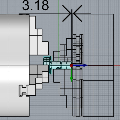
- In the Task List, expand Part Transfer.
A single command appears. - Click on the Part Transfer command, and set the Part Pickup Position in the Parameters group to
- At the bottom of the Lathe Wizard, click Finish.
Part 5) Simulate
We now simulate to verify the correct transfer positions in simulation.
- In the CAM Tree, right-click Mill Turn Job, and select Simulate.
The simulation launches. - In the Move List, click Op. 10: "Lathe Thread-60 DEG - LAY DOWN".
The simulation jumps to this operation. - Set the Simulation Run Speed slider to about 25%, (with 0% being all the way to the left).
- Click Run.
Notice the moves that occur after the threading operation.
These distances should coincide with the values we set for the:- Move Sub Spindle To Clearance: Moves toward the part.
- Start Fast Feed Up To Part: Moves closer to the part.
- Feed To Pickup Location: Arrives at the pickup location seen in the above image.
- Part Transfer: Same position as the Feed To Pickup Location.
- When the simulation finishes, set the Workpiece to Hide, and the Stock to Show.
The stock should appear as our part does in the first images of this example.
Congratulations! You have completed the Mill Turn Transfers Example. Much more information about Mill Turn jobs is available in this Help system.