


 Leads
Leads
Introduction
This topic explains the Leads page of the Drag Knife operation found in the 2 Axis Wizard.
 Leads
Leads
Entry
-
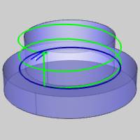
 Plunge - the tool plunges directly to the start
point of the toolpath. The Lead-in and Lead-out settings become available.
Plunge - the tool plunges directly to the start
point of the toolpath. The Lead-in and Lead-out settings become available.
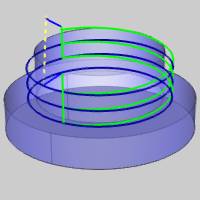
 Ramp
- creates a linear ramp move into the stock. The ramps are automatically
adjusted, based on values entered, so that collision into the model
is avoided. When this option is selected the following boxes become
available.
Ramp
- creates a linear ramp move into the stock. The ramps are automatically
adjusted, based on values entered, so that collision into the model
is avoided. When this option is selected the following boxes become
available.
- Angle of Approach - sets the angle of the toolpath ramp move. When using this option without defining a Maximum Length, the ramp is applied to the entire profile (from the toolpath start point to the top of feature).
- Maximum Length
 Select the check box to define the maximum horizontal distance over which
the ramp move is applied.
Select the check box to define the maximum horizontal distance over which
the ramp move is applied.
 Clear the check box when not limiting the length of the ramp move. The
ramp move is created using only the Angle of Approach.
Clear the check box when not limiting the length of the ramp move. The
ramp move is created using only the Angle of Approach.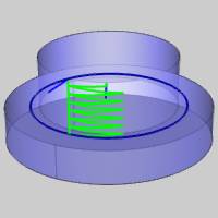
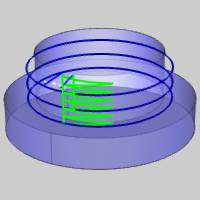
Warning: The Ramp approach type does not support collision detection or island avoidance. This should be used with caution.
Lead-in
-
Vertical - generates a plunge feed move into the feature.

Warning: The Vertical Lead-in type is not actually a lead-in as it only creates a plunge move into the feature. Most machine controllers cannot apply compensation commands to a vertical plunge (Z-axis) move. (G41/G42 are not output when using the Vertical Lead-in.)
-
Parallel - generates a linear feed move into the feature parallel to the toolpath
using the specified length.
- Length
- sets the length of the lead-in from the feature.
- Length
- sets the length of the lead-in from the feature.
-
Right Angle - generates a linear feed at a right angle to the
toolpath using the specified length.

- Length
- sets the length of the lead-in from the feature.
- Length
- sets the length of the lead-in from the feature.
-
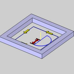
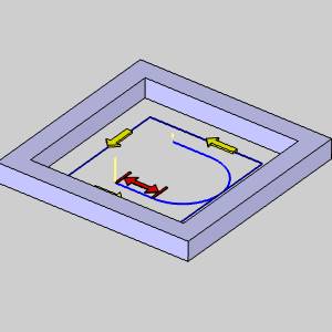
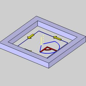
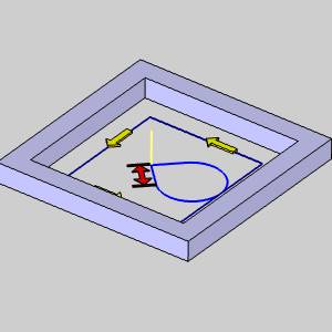
Circular - creates a linear move followed by an arc sweep into the start of
the feature. You have complete control over both the line move and
the arc move using the following settings.

Line
-
Right Angle - creates a line segment at a right angle to the arc.
- Length - sets the length of the line.
- Length - sets the length of the line.
-
User Defined - enables the Angle parameter for you to customize the angle of the line.
- Angle - sets the angle of the line segment.
- Length - sets the length of the line segment.
- Angle - sets the angle of the line segment.
-
Tangent - sets the Angle of the line to 0.00 degrees to the arc to make the line and arc tangent.
- Length - sets the length of the line segment.
- Length - sets the length of the line segment.
Arc
- Radius - sets the radius of the arc sweep into the start of, and out from the end of, the feature.
| Right Angle | User Defined | Tangent |
|

|
|
- Sweep Angle - sets the length of the sweep based on the angle of the arc.
| Right Angle | User Defined | Tangent |
|
|
|
-
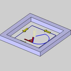
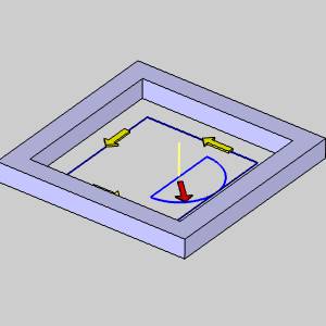
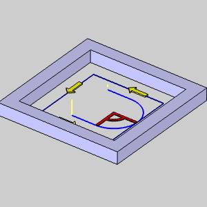
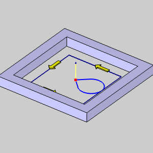
Blend - generates a linear move and then an arc move into the feature. This lead type can be used to lead-in and lead-out of the feature from the same point. The blend lead type creates a tangent path into the feature.
Line
- Length - sets the length of the line segment.
Arc
- Radius - sets the radius of the lead move into the start of the feature.
-
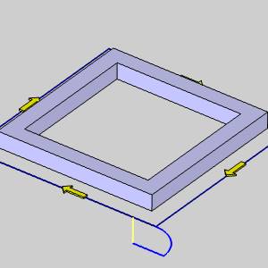
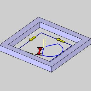
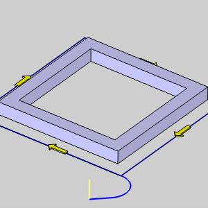
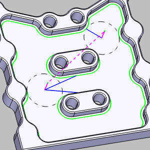
Point - generates a linear move from a point into the feature. The point can be a user-selected point, or an automatically generated center point and can be the same as, or different from the lead-out point.
Line
-
Lead from Center
Select this check
box to lead from the center of the resulting toolpath chains.
Clear the check box to ignore chain centers. Lead from Center Lead from Center
-
Pick Points - launches the Lead-in Points dialog allowing you to select custom points to assign to the toolpath chain(s).
-
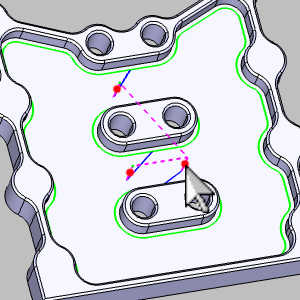
Point Blend - generates a linear move from a point into an arc of a specified radius which moves tangentially into the feature. The point can be a user-selected point, or an automatically generated center point and can be the same as, or different from the lead-out point.
Line
-
Lead from Center
Select this check
box to lead from the center of the resulting toolpath chains.
Clear the check box to ignore chain centers. Lead from Center
Lead from Center
-
Pick Points - launches the Lead-in Points dialog allowing you to select custom points to assign to the toolpath chain(s).
Arc
- Radius - sets the radius of the lead move into the start of the feature.
Note: The Point, and Point Blend leads are not available for operations used in a Mill Thread feature, or any of the Mill Hole features.
Lead-out
-
Same As Lead-in
Select this check
box to use the Lead-in settings to automatically set the Lead-out settings.
Clear the check box to set the Lead-out independently from the Lead-in.
-
Vertical - generates a vertical move out of the feature.
Warning: The Vertical Lead-out type is not actually a lead-out as it only creates a vertical move out of the feature. Most machine controllers cannot cancel compensation commands to a vertical (Z-axis) move. (G41/G42 are not canceled when using the Vertical Lead-out.)
-
Parallel - generates a linear feed move out of the feature parallel to the toolpath
using the specified length.
- Length
- sets the length of the lead-out from the feature.
- Length
- sets the length of the lead-out from the feature.
-
Right Angle - generates a linear feed at a right angle to the
toolpath using the specified length.
- Length
- sets the length of the lead-out from the feature.
- Length
- sets the length of the lead-out from the feature.
-
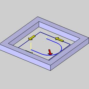
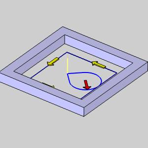
Circular - creates an arc sweep followed by a linear move at the end of
the feature. You have complete control over both the arc move, and the line move using the following settings.


Line
-
Right Angle - creates a line segment at a right angle to the arc.
- Length - sets the length of the line.
- Length - sets the length of the line.
-
User Defined - enables the Angle parameter for you to customize the angle of the line.
- Angle - sets the angle of the line segment.
- Length - sets the length of the line segment.
- Angle - sets the angle of the line segment.
-
Tangent - sets the Angle of the line to 0.00 degrees to the arc to make the line and arc tangent.
- Length - sets the length of the line segment.
- Length - sets the length of the line segment.
Arc
- Radius - sets the radius of the arc sweep out of the feature.
| Right Angle | User Defined | Tangent |
|
|
|
|
- Sweep Angle - sets the length of the sweep based on the angle of the arc.
| Right Angle | User Defined | Tangent |
|
|
|
|
-
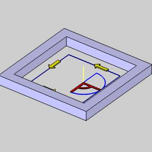
Blend - generates an arc move and then a linear move out of the feature. This lead type can be used to lead-in and lead-out of the feature from the same point. The blend lead type creates a tangent path out of the feature.
Line
- Length - sets the length of the line segment.
Arc
- Radius - sets the radius of the lead move from the end of the feature.
-
Point - generates a linear move from the feature to a point. The point can be a user-selected point, or an automatically generated center point and can be the same as, or different from the lead-in point.
Line
-
Lead to Center
Select this check
box to lead to the center of the resulting toolpath chains.
Clear the check box to ignore chain centers. Lead to Center
Lead to Center
-
Pick Points - launches the Lead-out Points dialog allowing you to select custom points to assign to the toolpath chain(s).
-
Point Blend - generates a tangential arc of a specified radius out of the feature into a linear move to a point. The point can be a user-selected point, or an automatically generated center point and can be the same as, or different from the lead-in point.
Line
-
Lead to Center
Select this check
box to lead to the center of the resulting toolpath chains.
Clear the check box to ignore chain centers. Lead to Center
Lead to Center
-
Pick Points - launches the Lead-out Points dialog allowing you to select custom points to assign to the toolpath chain(s).
- Overlap Amount - sets the length of overlap between the start point and end point of the toolpath to change the lead-in and lead-out locations.
Related Topics
Clicking Next> > takes you to the Corner Types page.