


Corner Slowdown Example 2
Introduction
This example will demonstrate many of the options found in the Corner Slowdown option found in the Advanced Feedrates page.
Example
In this example we have a completed part with toolpath, but would like to applied a slower feedrate in and around the corners of the part.
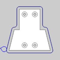
Part 1) Understanding the current toolpath
The current toolpath uses a particular feedrate which the user sets in the Tool page of the 2 Axis Wizard.This feedrate is applied to all feed moves in the toolpath.
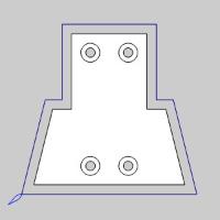
- In the CAM Tree, right-click the operation to be adjusted, and select Backplot.
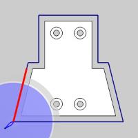
The Backplot dialog appears in the Data Entry Manager. - Click the Next button to move through the toolpath until the first long toolpath entity is highlighted.
Notice the move is highlighted all the way to the angle change, and also the Feedrate listed in the More Detailed Information group of the Backplot dialog, states Regular Feed. - Click Next twice more to see the same result with the next two toolpath entities.
- Click Close to exit the Backplot dialog.
Part 2) Updating the Corner Speed
In this part we update the speed in the corners to be fifty percent of the current feedrate, and set an eighth inch to be the distance from the corner where the slowdown is to be applied.
- In the CAM Tree, right-click the operation to be adjusted, and select Edit.
The 2 Axis Wizard appears. - Move to the Advanced Feedrates page and select the check box for Corner Slowdown.
The section becomes active. - Set the Distance from Corner to 0.125, and click Compute.
Part 3) Backplotting the result
In order to verify your results it is good practice to utilize the Backplot feature.
- In the CAM Tree, right-click the operation, and select Backplot.
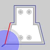
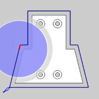
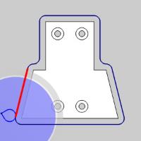
The Backplot dialog appears in the Data Entry Manager. - Click the Next button to move through the toolpath until the first long toolpath entity is highlighted.
Notice the highlighted move stops just shy of the angle change.This is the eighth inch distance we specified. - Click Next again.
Notice in the Feedrate listed in the More Detailed Information group of the Backplot dialog, states %50.00 Regular Feed.We can now see our feedrate has been reduced. - Click Next again.

Notice the following toolpath move is at the Regular Feedrate.Also notice this stops short of the angle change as well.Again, this is our Distance from Corner at work. - Click Next once more and notice our the remaining portion is at fifty percent of our feedrate.
- Click Close to exit the Backplot dialog.
Part 4) Understanding Distance from Corner and toolpath entity length
In this part we examine instances where our toolpath segment cannot be broken.
- In the CAM Tree, right-click the operation to be adjusted, and select Edit.
The 2 Axis Wizard appears. - Move to the Advanced Feedrates page and set the Distance from Corner to 0.250, and click Compute.
Part 5) Backplotting the result
- In the CAM Tree, right-click the operation, and select Backplot.
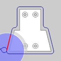
The Backplot dialog appears in the Data Entry Manager. - Click the Next button to move through the toolpath until the first long toolpath entity is highlighted.
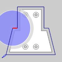
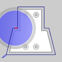
Notice the highlighted move stops much further from the angle change.This is the quarter inch distance we specified. - Click Next twice.
Notice in the entire toolpath segment is highlighted, and that is lists a 50.00% Regular Feedrate.This is because the toolpath segment is under the specified Distance from Corner.When this occurs the entire segment uses the reduced feedrate. - Click Close to exit the Backplot dialog.
Part 6) Using Arc Look Ahead Count
In this part we examine Arc Look Ahead Count.Since corners are found by comparing the angle of one toolpath segment to the next, and since arcs are normally tangent to the previous move, we can look use the Arc Look Ahead Count to check the current segment to the entity, or entities, ahead of the arc.
- In the CAM Tree, right-click the operation to be adjusted, and select Edit.
The 2 Axis Wizard appears. - Move to the Corner Types page and set both the External corners and Internal corners to Round, and click Compute.
Notice we now have arcs in all of the corners.In cases like these we must utilize the Arc Look Ahead Count, but first we will investigate the current result. - In the CAM Tree, right-click the operation, and select Backplot.
The Backplot dialog appears in the Data Entry Manager. - Click the Next button to move through the toolpath until the first long toolpath entity is highlighted.
Notice the highlighted move goes all the way to the corner.This is due to finding no angle between our line and the next tangent arc.We will now correct that. - In the CAM Tree, right-click the operation to be adjusted, and select Edit.
The 2 Axis Wizard appears. - Move to the Advanced Feedrates page and set the Arc Look Ahead Count to 3, and click Compute.
- In the CAM Tree, right-click the operation, and select Backplot.
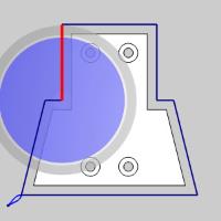
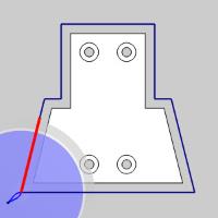
The Backplot dialog appears in the Data Entry Manager. - Click the Next button to move through the toolpath until the first long toolpath entity is highlighted.
We can see now that we are using the Arc Look Ahead Count, we recognize the arc as a corner and apply the slowdown.If you move through the remaining corner segments, you will notice each uses the reduced feedrate until the next full length toolpath segment shown below.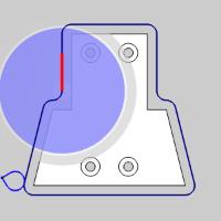
- Click Close to exit the Backplot dialog.
Part 7) Using # of Divisions
Another useful feature of the Corner Slowdown function is the # of Divisions.With this option, you can choose to divide the Distance from Corner value into equal parts, so the slowdown occurs gradually throughout the specified distance until the full feedrate reduction is reached on the last division.
- In the CAM Tree, right-click the operation to be adjusted, and select Edit.
The 2 Axis Wizard appears. - Move to the Advanced Feedrates page and set the # of Divisions to 3, and click Compute.
- In the CAM Tree, right-click the operation, and select Backplot.
The Backplot dialog appears in the Data Entry Manager. - Click the Next button to move through the toolpath until the first long toolpath entity is highlighted.
- Click Next again.
Notice this highlighted segment is much smaller, and that is lists a 83.33% Regular Feed. - Click Next again, and notice the 66.67% Regular Feed listed.
- Click Next again, and notice the 50.00% Regular Feed listed.
Since we used a value of 3 for our # of Divisions, the Distance from Corner has been divided into three distinct segments, each decreasing the feedrate linearly until the full slowdown percentage is achieved on the last segment.
This concludes the example.