 Patterns
Introduction
This topic explains the Patterns page of the Steep Shallow operation found in the Mill 3 Axis Wizard.
 Patterns
Cut Pattern
Strategy
-
 Z Level + Planar - utilizes the Advanced Z Level Finish for steep areas while the shallow areas utilize the Planar.
 -
 Z Level + Equidistant - utilizes the Advanced Z Level Finish for steep areas while the shallow areas utilize the Equidistant Offset.
Shallow Region
- Angle Limit - determines the amount of angle a surface can have to be considered a Shallow Region.
- Planar Lace Angle - determines the direction of the toolpath passes in reference to the machining origin. The default value of 90 degrees generates passes that are parallel to the Y-axis, and a value of 0 degrees generates passes that are parallel to the X-axis of the machining origin.
Note: The Planar Lace Angle, and the Optimal Lace Angle options are only available when the Z Level + Planar strategy is selected.
Start From
-
 Top - starts the operation from the top
of the model and cuts down to the bottom.
 -
 Bottom - starts the operation from the bottom of the model
and cuts up to the top.
Cut Direction
- Independent Methods - allows you to set cut direction to the overall job, or to the steep and shallow regions independently.
 With this check box selected, cut directions for both Steep Region and Shallow Region are available.
 Clear the check box to apply the same cut direction for entire operation.
Method
 Zig
- creates the operation so each pass of the tool follows the same
general direction (one way machining).
 Zig Zag
- creates the operation so each pass of the tool alternates direction
from the previous pass.
Note: The following two options are only available when the Zig Method is selected.
-
 Climb
Mill - the tool travels in a counter
clockwise direction along the inside shapes of the model and travels
in a clockwise direction along the outside edges of the model.
 -
 Conventional Mill - the tool travels in a clockwise direction
along the inside shapes of the model and travels in a counter clockwise
direction along the outside edges of the model.
Corners
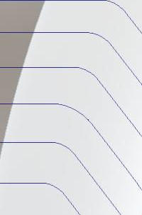
- Round Corners - The Round Corners option allows you to specify a maximum deviation value
which allows a radius within that range to be substituted in place of
sharp corners. To turn this option on, click the Round
Corners check box. You can then type the maximum deviation possible
for the round corners in the Maximum
Deviation box. To turn this option off, clear the Round Corners
check box.
|
|
|

|

|
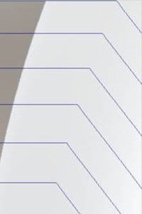
- Sharp Corners - The Sharp Corners command allows you to force a sharp angle change in the toolpath which otherwise may have been rounded.
|
|
|

|

|
Next Topic
From the Patterns page in the Wizard, click Next>> to go to Parameters page.


