


Surface paths: Multiaxis Machining
Introduction
This topic will explain the options found in the Surface paths tab of the Multiaxis Machining operation.
Surface paths
The Surface paths tab allows you to define the machining pattern, the order of the cuts, the depth and stepover used by the cuts, as well as defining the area to cut and the handling of undercut areas.
Pattern
- Machining- select from one of the following operations.
- Roughing - Removes the bulk of the material with multiaxis moves.
- Floor Finishing - Finishes the floor surfaces with multiaxis moves.
- Wall Finishing - Finishing the wall surfaces with multiaxis moves.
- Rest Finishing - Finishing the areas previous operations could not reach. The operations used to calculate the area for rest finishing are selected by opening the 3d containment dialog, choosing the Auto Containment option, and clicking the Previous operation button. The Operation List dialog is then opened allowing you to select the operations to be considered when calculating the area requiring the rest finishing.
- Roughing - Removes the bulk of the material with multiaxis moves.
- Pattern- select from one of the following strategies when using Roughing, Floor finishing, or Wall finishing.
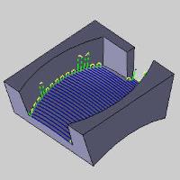
- Offset from floor - When using the Roughing, this option creates parallel cuts that are offset from the selected Floor Surface.
- Offset from ceiling - When using the Roughing, this option creates parallel cuts that are offset from the selected Ceiling Surface.
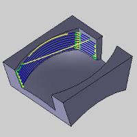
- Morph between ceiling and floor - When using the Roughing or Wall finishing, this option creates cuts that morph or blend between the Ceiling and Floor Surfaces. (The Ceiling Surface button becomes available on the Part Definition tab when this option is selected.)
- Offset from wall - When using the Floor finishing, this option creates an offset of the wall to apply the finish to the floor.
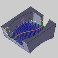
- Parallel - When finishing, this option will create an offset of the selected Guide curve.
- Offset from floor - When using the Roughing, this option creates parallel cuts that are offset from the selected Floor Surface.
- Type
- Offset - When using the Roughing, this option creates a standard offset pattern from the selected geometry.
- Adaptive - When using the Roughing, this option creates the feature using the Adaptive high-speed machining strategy. The constant tool engagement is automatically calculated for the feature.
- Offset - When using the Roughing, this option creates a standard offset pattern from the selected geometry.
- Guide curve
- Longest dimension - When using the Floor finishing with a Parallel pattern, this option will identify and utilize the longest edge of the floor in order to create a parallel pattern from.
- Floor curve - When using the Wall finishing with a Parallel pattern, this option will utilize the edge of the floor in order to create a parallel pattern from.
- Ceiling curve - When using the Wall finishing with a Parallel pattern, this option will utilize the edge of the ceiling in order to create a parallel pattern from.
- User defined drive - When using finishing with a Parallel pattern, this option will allow you to select custom geometry to create a parallel pattern from.
- Longest dimension - When using the Floor finishing with a Parallel pattern, this option will identify and utilize the longest edge of the floor in order to create a parallel pattern from.
Sorting
-
Cutting method
-
Zigzag- creates a toolpath with an alternating cutting direction.
-
One way - creates a toolpath that only cuts in one direction. A retract and rapid move is created at the end of each toolpath slice.
-
Intermediate slices - These options become available when selecting the check box for Intermediate slices in the Advanced dialog of the Depth step group.
-
After each depth step - forces the available intermediate steps to be cut after each depth step of the roughing operation.
-
After last depth step - forces the intermediate steps to be handled at the same time after all depth steps of the roughing operation have been completed.
-
-
Direction for one way machining - when using the One Way cutting method, set the cutting direction to Climb or Conventional.
-
Machine By - select one of the following options to define the order of cuts.
-
Levels- cuts the entire part to one depth before moving on to the next depth.
-
Regions- cuts each region of the part to the total depth before moving on to the next region.
-
Stepover
The parameters used to define the stepover change slightly depending on the selected pattern settings.
With Offset
-
Maximum stepover - is the not-to-exceed distance between each toolpath slice.
-
Cusp height - is used to define the stepover value using a cusp height instead of a distance when using a ball endmill.
With Adaptive and One Way
-
Maximum stepover - is the not-to-exceed distance between each toolpath slice.
-
Desired stepover - is the optimal stepover for the feature which is used as much as possible.
With Adaptive and Zig Zag
-
Climb stepover (%Stepover) - is the percentage of the Stepover value that is applied to climb cutting passes.
-
Conventional stepover (%Stepover) - is the percentage of the Stepover value that is applied to conventional cutting passes.
Depth Step
To define the depth steps of the feature, select one of the following two options.
-
Constant depth step - determines the maximum amount of material removed for each pass. Type the positive value that you want to use for each depth step. The software automatically calculates the appropriate number of steps.
-
Number of slices - type a number of slices (or passes) to define the depth of cut for the feature. The software automatically calculates the depth steps value.
-
Advanced- opens the Depth Step dialog box for you to further define the depth step with advanced options as follows.
-
First Depth Step
 Select the check box to define a cutting depth for the first cut depth only. Type the value that you want to apply to the first depth step.
 Clear the check box when the first cut is the same as all other cuts.
 -
Final Depth Step
Select the check box to define a cutting depth for the last cut depth only. Type the value that you want to apply to the last depth step. Clear the check box when the final cut is the same as all other cuts. -
Value
Select the check box to type specific values at which the depth steps are created. When you select this option, a table displays for you to add values (Z-axis). Right-click anywhere in the table to access a shortcut menu for adding or removing items. After adding an item, set the desired value for it. Clear the check box to turn off the value depth step option. -
Intermediate Slices
Select the check box to define intermediate slices using one of two options. Clear the check box when not using intermediate slices.-
Constant depth step - automatically creates intermediate slices based on a value (depth) you define. Type the depth step value applied to create a stepped machining in any area with rest material.
-
Number of slices - automatically creates intermediate slices based on a number of slices you define. Type the number of slices to use in the box to create stepped machining passes in area with rest material.
-
Area
After creating a roughing operation, you can create a second operation with Rest Roughing that uses a smaller tool than the first roughing operation. The system automatically finds and applies the toolpath only to the areas not machined by the previous tool.
- Rest Rough
Select the check box to turn on the rest-roughing option. To open the Rest Roughing dialog box and define the parameters, click Rest Rough. Clear the check box to turn off rest roughing.- Roughing Tool Diameter - type the diameter of the previously used roughing tool.
- Roughing> Tool Corner Radius - type the corner radius of the previously used roughing tool.
- Roughing Offset - type the offset value of the previously defined roughing operation.
- 3d containment - When Rest finishing is selected, no check box is available. This is because the 3d containment is not optional to achieve a result. Select the check box to turn on 3D containment which allows you to assign a 3-dimensional curve to define the boundary for the operation. Clear the check box to turn off 3D Containment.


- The 3d containment dialog - Click 3D Containment to open the dialog. Ever pattern besides Rest finishing only provides a Manual option, while Rest finishing provides Manual and Auto:
- Manual - click the 3d Containment button to launch the Select Geometry dialog and select the geometry to define the boundary to be used. Select the geometry from wireframe or surface edges, and confirm the selection to return to the wizard. The resulting toolpath is contained within the boundary, but be aware that the current stock definition may cause cutting outside of (above) the boundary if there is stock to be removed.
- Auto - click the Previous operation button to launch the Operation list dialog. This dialog lists the operation names available to calculate the rest finishing from. Ideally this would be a wall finishing operation and a floor finishing operation. If the Create Boundary Geometry check box is selected, the boundary geometry will be created
- The 3d containment dialog - Click 3D Containment to open the dialog. Ever pattern besides Rest finishing only provides a Manual option, while Rest finishing provides Manual and Auto:
- Undercuts - dictates if undercutting is handled. Choose between:
- Do not machine - will prevent undercut areas from being handled in the toolpath.
- Machine - will include undercut areas in the toolpath.
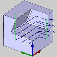
- Machine only - will only handle the undercut area and exclude all other toolpath.
- Do not machine - will prevent undercut areas from being handled in the toolpath.
- Extend undercuts - allows you to define an extra area to be handled, beyond the undercut itself, when the Machine only option is used.


| Machine only | Machine only with extension |

|

|