


Tool Angle Control
Introduction
This topic explains the Tool Angle Control dialog box that is accessed from the Tool page of the Lathe Wizard for Mill Turn jobs. This dialog box is used to specify the rotation angles for both the milling head and turning (lathe) tool attached to it for multiaxis mill turn machines that have a milling spindle head.
Navigation
To open the Tool Angle Control dialog box:
-
Navigate to the Tool page for any lathe operation in the Lathe Wizard.
-
Under Machining Data, click the Tool Angle Control button.
The Dialog Parameters
The following settings are only used to define the rotation angles for the milling spindle/head and tool for an operation on a multiaxis mill turn machine (often called a B-axis head).
Head Control
The Head Control group defines the rotation angle of the milling spindle/head that is used for the operation from which you opened the Tool Angle Control dialog box.
Angle
The angle value determines the (usually B-axis) rotation angle of the milling head for the operation. Next to Angle, click the down arrow to select an angle from the list as follows.
-
You can select a predefined -180, -90, 0, 90, or 180 from the list, or you can select User Defined to type any other value.
-
When User Defined is selected, type a value in the angle box to define a custom angle.
The rotation angle that you use for a milling spindle is based on where the machine controller defines zero degrees. The two most common zero degree orientations for a milling spindle on the machine are shown next.
|
Milling Spindle Zero Degree Orientation (Z Axis) |
Milling Spindle Zero Degree Orientation (X Axis) |
|
|

|

Head Control Angle Example
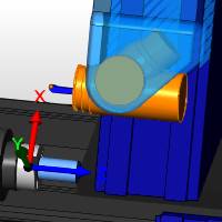
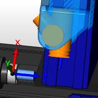
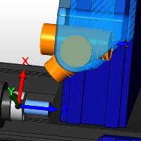
The following image shows a milling head where the zero degree orientation aligns the head to be parallel with the machine Z-axis (as shown in the first of the two previous images). The remaining images show the orientation of the head at 90 and 180 degrees for this machine (note that the rotation angles are not the same for all machines).
|
Head Angle = 0 Degrees |
Head Angle = 90 Degrees |
Head Angle = 180 Degrees |
|
|
|
Tool Orientation Control
The Tool Orientation Control group defines the rotation angle of the tool mounted in the milling spindle/head for the operation from which you opened the Tool Angle Control dialog box.
Angle
The angle value determines the tool orientation for the operation. Next to Angle, click the down arrow to select an angle from the list as follows. Note that the mounting orientation that you define for the tool in the tool crib is used as the zero degree rotation value in the software.
-
You can select a predefined 0 or 180 from the list, or you can select User Defined to enter any other value.
-
When User Defined is selected, type a value in the angle box to define a custom angle.
Tool Orientation Angle Example
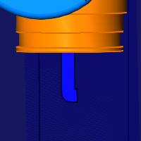
The tool orientation angle depends on a few settings, such as the mounting position in the tool crib and the machine, but the following provides one example of the tool orientation for a lathe tool attached to the milling head. For the example shown, the zero degree tool orientation points in the negative Z-axis direction and the 180 degree tool orientation points in the positive Z-axis direction.
|
Milling Head = 90 Degrees (Shown for reference) |
Tool Angle = 0 Degrees (Same as shown in Tool Crib) |
Tool Angle = 180 Degrees |
|
|

|
|