


What's New in BobCAM for Rhino V3
Introduction
The new BobCAM for Rhino V3 has a ton of new features and even enhancements to existing features! Craft your art projects more easily with the redefined workflow of the all new BobART user interface! For those requesting more control of the operation posting order, including how toolpath patterns are posted, we decided to completely rethink this portion of the software and are introducing the new Operation Tree and Tool Tree to give you all the power and control you need. Oh, and we’ve got Finishing Spring Passes, brand new Leads with point picking and automatic lead from center options, and new features and enhancements in 2, 3, 4, and 5 Axis. Whether you’re a new customer, or already part of the family, this version is going to make you glad you’re here!
New Features
BobART
BobART has received a long overdue workflow overhaul to help you get the results you're looking for without the hassle!
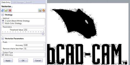
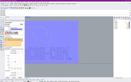
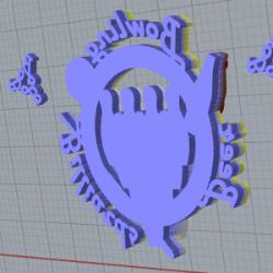
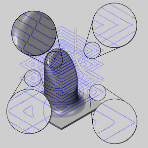
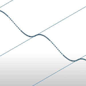
| When vectorizing images in the past, the Raster to Vector dialog was a floating window with a static image to give you an idea of the detail you were pulling from the image to create the geometry with. This method had its downsides as you could not adjust your view of the image being used. In this latest release the Vectorize dialog is opened directly in the Data Entry Manager which allows you to view the image in the graphics area as you normally would. Zoom in, Pan, and even Rotate to put as much focus on the area whichever areas interest you the most! | |
|
|
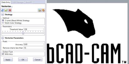
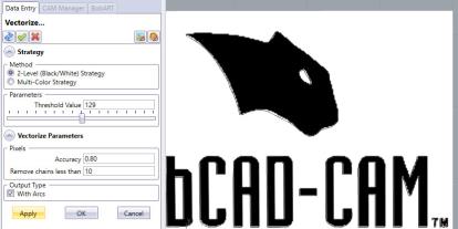
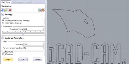
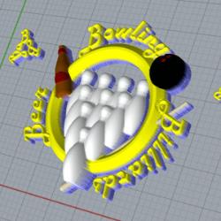
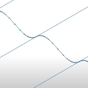
| Since previous versions did not allow you to zoom in on the image, vectorization may need to be done several times to get the desired results. In those circumstances you'd need to right-click the image and select Vectorize again to reopen the dialog, adjust results and click OK again to double check the results once more. In this version we did away with the tiresome back and forth and allow you to instantly review your results before you ever exit the Vectorize dialog. Simply click Apply, Blank the image, check your results in the graphics area and adjust as needed. Once you get the results you need, click OK and you're done. | |
|
|
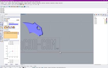
| With the new and improved BobART dialogs you can regenerate the canvas without exiting! In the past, creating emboss features consisted of selecting the feature, setting the parameters, exiting the dialog to add geometry to each of the applicable feature items in the BobART Tree, and then regenerating to view the result. This could be a little frustrating, especially if you needed to adjust the selected geometry and the parameters. Now, you deal with a single dialog and can make sure you're happy with the result before you ever exit! | |
|

|
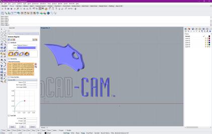
| To improve an already amazing workflow, we've added automatic regeneration! Once you think you think you have the parameters where you 'd like them, click Apply to update the canvas. Now, anytime you add geometry, the canvas is regenerated with the new geometry and with whatever parameters you may have adjusted in the meantime! | |
|
|
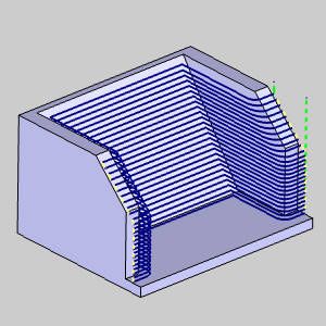
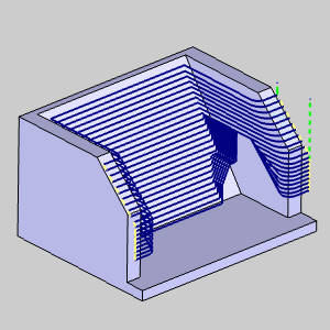
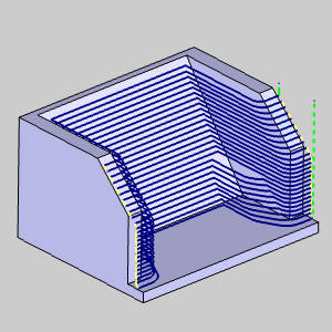
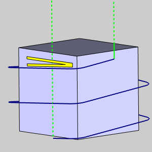
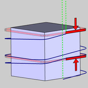
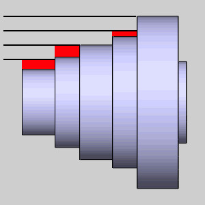
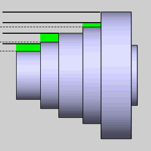
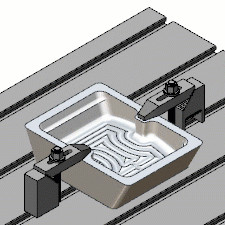
| Oh, and did we mention we now have a "Make as Solid" option? In the past, while you could do things to give a height to your model, extended walls were really the only thing added. You were still left with what was essentially a mesh surface draped down to the floor. Looking behind the model, as seen in the first image, it was apparent the mesh was not closed. With this new option, as you can see in the following image, the mesh is closed creating a water-tight mesh. This expands the possibilities of what can be done with your final model, and we've even added unit options allowing you to specify the units to use when exporting STL Components! | ||
|
|
|
CAM
General
Operations Manager
The new Operations Manager brings a whole new way to manage your jobs!
Operation Tree

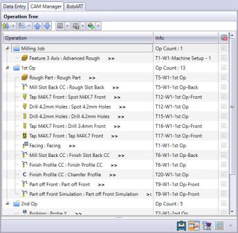
|
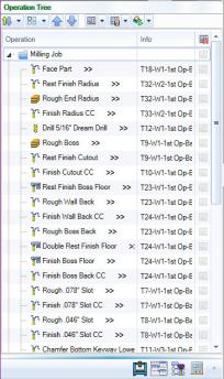
The Operation Tree is now your go-to place for all your posting needs! We've always been a feature-based CAM system, and this meant the order of your machining operations didn't always correlate to the order you've created them in the CAM Tree. In previous versions, this was managed in the Machining Order dialog which allowed you to sort the operation posting order. In this latest release the Machining order dialog has been replaced by a complete Operation Tree which enhances the workflow in the software in many ways that were never possible: |
-
See all jobs and their operations regardless of their posting status
In the past operations that we set to not post were not shown in the Machining Order dialog. This could cause confusion about their posted position once their posting status was reinstated. With the Operation Tree, you see all operations and their current posting status. -
Edit Operations
While reviewing your operations in the Operation Tree you might notice something you'd like to update in the toolpath. With the new Operation Tree, you can simply right-click the operation and select Edit to launch the wizard! Adjust anything you need and click Compute! -
Post Yes/No flags can be seen and managed
Not only can you see which operations are set to post and which are not, you can also control these states directly in the Operation Tree. By selecting multiple operations, you can even update the state of several operations at once! -
Multi-select functionality
Use the standard Ctrl/Shift keyboard modifiers to select multiple operations at once. Once selected you can update their posting status simultaneously, drag and drop to update their order, simulate them, and even post them! -
Manage patterned operations
In the past the Machining Order dialog did not display, let alone allow you to manage, the individual patterned instances of an operation. If the pattern is set to post in the CAM Tree, the Operation Tree will allow you to update their individual posting state, adjust their posting, simulate them, and post them! -
Show or hide all patterned operations
The toolpath patterns can easily be hidden and shown with the Toolpath Pattern Options in the Quick Access menu of the Operation Tree.-
Control whether hidden patterns should be posted
When deciding to hide patterned operations we provide an additional option which allows you to determine whether the hidden operations should be posted.
-
-
New toolpath pattern sorting options
Along with the check box to adjust their visibility are the options to automatically adjust their posting order with the Operation Priority and Feature Priority buttons. -
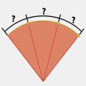
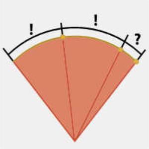
Posting Order Violation warning
The new Operation Tree gives you complete control of the posting order, even allowing you to violate the usual posting rules preventing finishing operations from posting before their associated roughing operations. When moving operations in the operation tree, you'll automatically be prevented from moving your finish before its rough unless its set not to post. Once reordered, and set to post, warning icons (
 ) will be shown to alert you to the violation and attempting to post will show you a warning message to alert you to the issue once more. But we assume you know what you're doing, so just click *Yes and we'll post it just the way you have it.
*BobCAD-CAM and it associated partners bear no responsibility for any broken tools, or exploded machines. -
Simulate entire jobs, groups of operations, or individual operations
Simulating what you need has never been easier. In the past, simulating a single operation, or a couple operations meant everything else had to be set to Post No. Now, simply select what you want and choose Simulate Selected! -
Create setup sheets for entire jobs, groups of operations, or individual operations
Just like you can create setup sheets in the CAM Tree, you can also create setup sheet in the Operation Tree! Unlike the CAM Tree though, you don't need to go through each operation you don't want in the setup sheet and change its posting state to Post No. Just highlight the operations you want on the setup sheet along with the job, right-click and choose Generate Selected Setup Sheet! -
Post entire jobs, groups of operations, or individual operations
The Operation Tree allows you to easily post exactly what you need directly! Right-click a job and select Post to post everything. Select a single operation, or even multiple operations at once, right-click and Post.
Display Feature Name
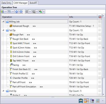
By default, the operation tree only lists the operation names, but we have found that many users don’t typically rename their operations, and organize their CAM data by naming their features only. So, if this sounds like you, we have the option in settings to also display the feature name.
|
|
|
|
|
Tool Tree

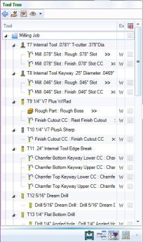
|
The Tool Tree is your one-stop shop for everything tool related. Once you've created your jobs in the CAM Tree, open the Tool Tree to see all your jobs, the tools in their tool crib, and which operations are assigned to each tool! |
-
 Access the Tool Cribs
With all your jobs available, simply highlight part of that job and click the Tool Crib button in the quick access menu to open the Tool Crib dialog and view all the tools in the job. -
 Add Tool to the Tool Crib
With all your jobs available, simply highlight part of that job and click the Add Tool to the Tool Crib button in the quick access menu to open the Tool Library dialog and choose a tool to automatically add to the current Tool Crib.
-
 Access the Tool Library
Click the Tool Library button in the quick access menu to open the Tool Library and view available tools, add tools, or edit existing tools with ease. -
Post all operations for a tool
In some cases, you may want to post the operations which are utilizing a particular tool. This has never been easier with the Tool Tree! Simply right-click the tool, select Post this Tool's Operation(s), and all operations under that tool are posted instantly. -
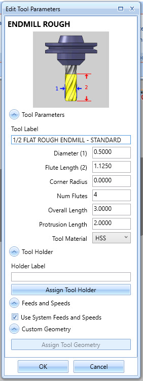
Editing tools - The Edit Tool Parameters dialog
Did something change and now you need to edit aspects of the tool being used in several operations? No problem! Simply right-click the tool and select Edit. The Edit Tool Parameters dialog opens allowing you to edit the necessary aspects of the tool being used. Depending on the values being changed computing the toolpath again may be required. Simply right-click the tool and select Compute All Toolpath. This same dialog can also be edited through the Tool Crib! -
Replacing tools
Did something change and now you need to update the tool being used in several operations? No problem! Simply right-click the tool and select Replace. You'll then be presented with a message telling you it's in use and asks if you want to change the tool in all operations that use it. Click Yes, and the Tool Library launches, allowing you to pick your replacement. Pick the new tool, click OK and your tool is updated. Now right-click the new tool and select Compute All Toolpath. -
Compute All Toolpath
When you update tools, operations which utilize that tool need to be recomputed. In the past this could be annoying since you would need to find the operations that use that tool and recompute them. And in previous version, no identifiers were placed on the operations in the CAM Tree to help you identify which operations needed to be recomputed for the new tool parameters. With the Tool Tree, all operations which need to be recomputed are identified with a warning icon. Plus, the operations are marked everywhere they are visible, in the CAM Tree, in the Operation Tree, and of course in the Tool Tree! Now, simply right-click the new tool and select Compute All Toolpath. All the operations under this tool are computed with the new tool parameters! -
Edit Operations
While reviewing your operations in the Tool Tree you might notice something you'd like to update in the toolpath. With the new Tool Tree, you can simply right-click the operation and select Edit to launch the wizard! Adjust anything you need and click Compute! -
Move Operations
In some cases you may notice an operation under the tool which should be utilizing a different tool. Right-click the operation and select Move To and the Tool Selection dialog launches to display all the tools in your Tool Crib. Select the proper tool and select OK. You can even just drag the operations to the tool you'd like it to utilize! That operation will now show under the newly selected tool with an icon showing it needs to be recomputed. Right-click, select Compute Toolpath, and you're done!
Editing Tools in the Tool Crib - The Edit Tool Parameters dialog
Updating tool values in your Tool Crib has never been easier with the new Edit Tool Parameters dialog! In the past, any edits to your tools were either done directly in the library, or in the tool page of your operations. When setting up tools in your tool crib, there was not a way to directly update their parameters. Now, with the Edit Tool Parameters dialog, just highlight the desired tool in your Tool Crib, and click Modify. The Edit Tool Parameters dialog opens, allowing you to update any of its associated values. Then, just click OK to confirm!
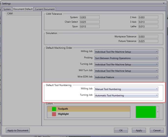
Default Tool Numbering
A new setting has been created which allows you to set the default tool numbering behavior for new Mill and Lathe jobs. In the Document Default and Current Document tabs, you'll now find the Default Tool Numbering group on the CAM page. This group gives you two setting to choose from for both milling and turning jobs: Automatic Tool Numbering, or Manual Tool Numbering. The setting simply determines whether the Use automatic tool numbering option in the Tool Crib and the Assigned Tools dialog is selected. In the past, both locations had Use automatic tool numbering selected by default. Based on customer feature requests, we've now put the power in your hands to decide whether that should be the case for your future jobs. Choose Automatic Tool Numbering, and the option will be selected by default resulting in tools added to the Tool Crib being number sequentially. Select Manual Tool Numbering, and tool numbers will be read from the tool library as they are added to your Tool Crib. Whichever way your work, these settings have you covered!
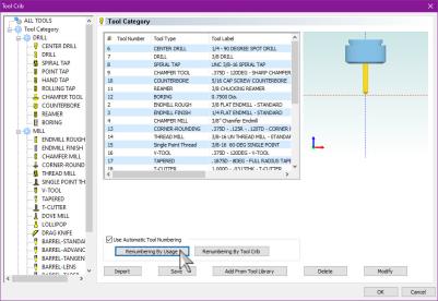
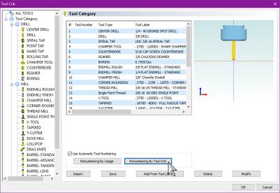
Use Automatic Tool Numbering : Renumbering
Two new actions have been added to the Use Automatic Tool Numbering group for your Mill and Lathe jobs to allow you to renumber your tools based on their use, or the order they were added to the Tool Crib. One of our main focuses for this release has been to make sure selecting, numbering, assigning, and editing your tools is as quick and intuitive as possible. We found even when using automatic tool numbering things can get a little confusing when removing and adding more tools to your crib. To solve this, we've created the renumbering actions so the numbers can be updated easily, and accurately. Whether you want them numbered as they were added to the Tool Crib, or as they are used in operations, simply click the associated button and your tool numbers are updated!
Tool Assignment
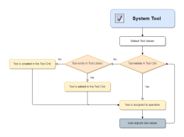
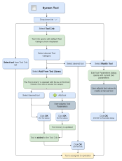
In this release, we've made some updates to the Tool page of your operations to make assigning and modifying tools simpler and more intuitive. Finding a good balance between giving users manual control with no assistance and an automatic system with no user input can be difficult, but we think we've found that balance with this updated tool page! The recommend workflow has been, and continues to be, to add the tools for the job to your Tool Crib prior to feature creation, but the updated Tool page makes grabbing those tools, modifying them, and even adding tools, easy to do and understand. Choose the flow that works for you. Below, you'll see the steps when the System Tool option is selected, and when it is not. Click the flow chart next to each to open it as its own topic. Use the link at the bottom to jump back, or close the new tab.
|
|
|
|
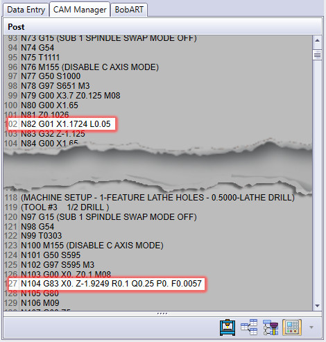
MDI
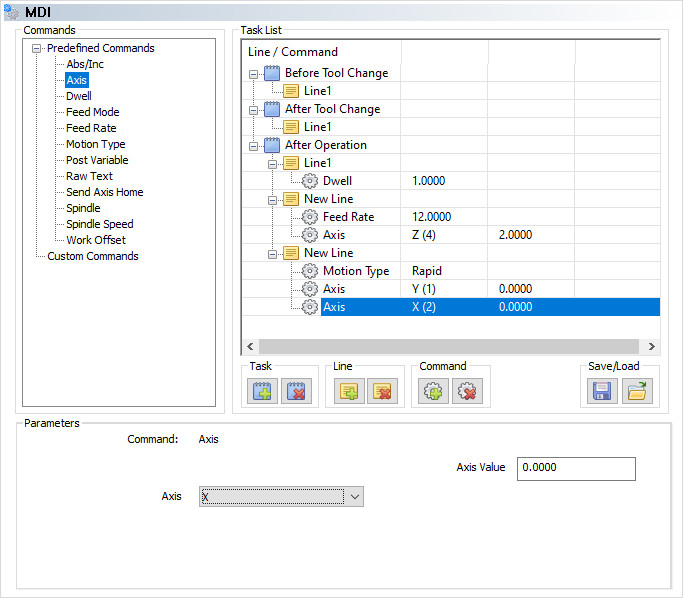
For the first time ever, Mill and Lathe jobs also support MDI, or manual data input, which allows you to manually define machine movement as needed for your machining operations. MDI allows you to build lines of code by deciding where to add the new lines, and what commands should be in those lines. In the image below, you can see we have added a dwell after the operation, and raised the Z axis at a specified speed before rapiding to X0,Y0. These task lists can customized however you need them, saved, and reloaded to any operation necessary, giving you the control you need to get the results you want!
CAM Tree Blank and Post Yes/No Icon State Update
A third state for parent items in your Extended CAM Tree has been added to give you even more information at a glance! When we first introduced the Extended option for your CAM Tree in the Settings dialog, it was an immediate hit. Not only did it add some visual organization to the visual/posting states of your CAM Tree items, but it also allowed you to update those states without having to access a context menu to do so. This version has improved upon that by adding a third state to parent items that shows whether all child items are selected or cleared. In the past, child items could be selected and cleared independently of the parent item. This could be a little confusing with a collapsed tree. Now, whether all child items are cleared, or selected, the parent item is automatically updated. When child items are in mixed states, the parent will show a third state:
-
Third State - This state exists only for parent items and shows the child items are a mix between selected and cleared states.
-
Selected - For child items, this shows the item is selected. For parent items, this shows all child items are selected.
-
Cleared - For child items, this shows the item is not selected. For parent items, this shows no child items are selected.
| Blank/Unblank | Post Yes/No | |||||
|

|

|
Toolpath Pattern Suppression
Previously toolpath patterns were “suppressed” by using the Post Yes/No options because either all instances of the pattern were going to be posted or none, but with the introduction of the operation tree and being able to manage individual instances of the patterns, we needed to clarify the meaning in the CAM Tree. So now from the CAM Tree you do not change the posting status of a toolpath pattern, you either suppress it or not to make the toolpath pattern operations available in the operation tree.
|
|
Suppressed toolpath patterns are shown with the Suppressed icon in the CAM Tree. |
Mill
Mill Express
New Leads
Point
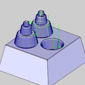
The new Point lead allows you to select a user defined point, or points from the graphics area to define the start and end points of the toolpath. In the past users have been able to add straight leads with the parallel and Right Angle lead options, but besides being able to set the chain start point and the length of those leads, there has not been a way to select a particular location for the start and end that isn't in line with those constraints. In this latest release, simply select Point and select Pick Points to launch the Lead-in/out Points dialog. Set your points, click OK and you're done. 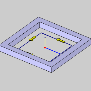
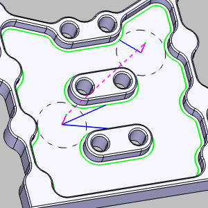
Point Blend
The new Point Blend lead allows you to select a user defined point, or points from the graphics area to define the start and end points of the toolpath. In the past users have been able to add leads which arc into the toolpath with the Circular and Blend lead options, but besides being able to set the chain start point and the length of those leads, there has not been a way to select a particular location for the start and end that isn't in line with those constraints. In this latest release, simply select Point Blend and select Pick Points to launch the Lead-in/out Points dialog. Set your points, click OK and you're done.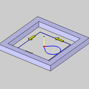
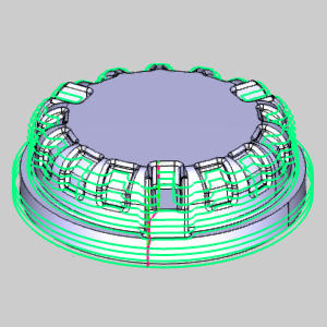
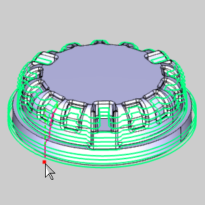
Lead from Center
By default the Lead from Center option allows you to utilize the center most positions of the created toolpath chains. In the past creating leads that started/ended in the center of the chain could be a little more challenging than you'd initially think. In fact, customers requesting the ability to do this easily is what lead to these new lead types! So here you go! Lead from Center made easy! No need to measure areas and calculate leads. 
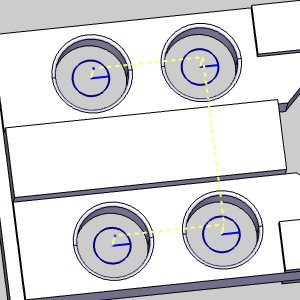
These leads work on any shape to find the center-most point created by the chains! 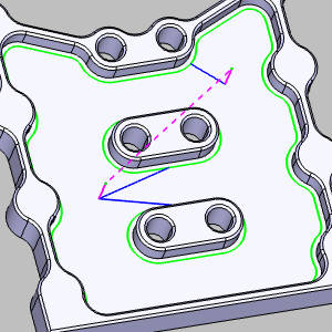
The Lead-in/out Points Dialog
The new dialog allows you to select points to assign to the toolpath chains. 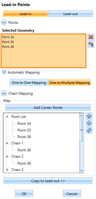
-
Automatic Mapping - automatically assigns points to the chains.
-
One to One Mapping - prevents multiple chains from using the same point.
-
One to Multiple Mapping - allows multiple chains to use the same point.
-
-
Add Center Points - assigns each inside chain a center point.
-
Map - This area lists all selected points and chains and allows manual control:
-
Drag points to the intended chain
-
Move points with the up/down buttons
-
Delete points from their currently assigned chains
-
Delete points from the Selected Geometry list
-
Add Center Points to chains
-
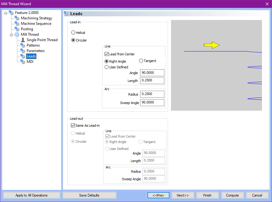
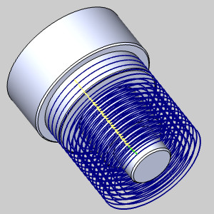
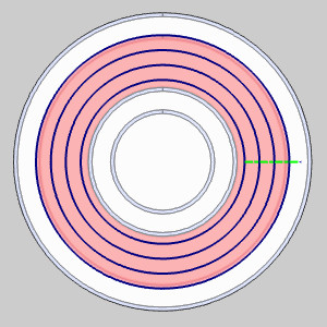
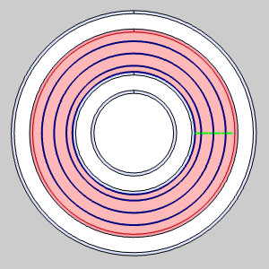
Thread Leads
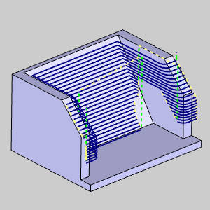
Additional lead options are now available in the Mill Thread operation! When using the inside thread type in previous versions, the Helical and Circular lead options allowed you to adjust the radius, but began and ended in the center. Although this is normally exactly what you would want, an obstacle in the center would create an issue. Now, whether you're using the Helical or Circular lead types, you can utilize the same Right Angle, Tangent, and User Defined options you're familiar with from other 2 Axis operations! Each one of these can be used with or without the Lead from Center option so you can get the specific leads you need regardless of the situation.
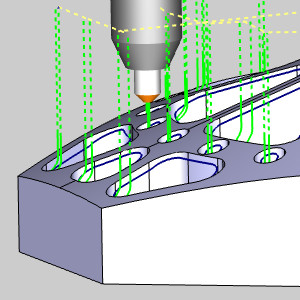
Spring Passes
For the first time ever, this latest release offers a Spring Passes option to make finishing easier than ever! Usually when finishing vertical walls, spring passes are applied to ensure tool deflection and chatter haven't had a negative impact on the result. In the past, this meant needing to apply a couple extra operations to the feature to behave as the spring passes. Now, this can all be done automatically in the same operation with a simple check box. Simply select Spring Passes, set the Number of Passes, and decide whether to apply the spring passes to all depth cuts and whether the leads should be applied prior to these spring pass. The operation will then automatically make those additional passes at the final profile to give you the spring passes you need! Spring Passes are available for the following operations:
-
Profile Rough
-
Profile Finish
-
Chamfer Mill
-
Corner Rounding
| Two Additional Operations (old method) |
|
|
|

|

|
| Full retract to clearance each pass | Retract to clearance each pass | No retract between passes |
Drag and Drop Toolpath Patterns
Updating what a Toolpath Pattern is applied to just got a lot easier with our new drag and drop functionality! Toolpath Patterns can be a huge time saver, but occasionally you may find you could have placed it a little more efficiently. In some cases, perhaps you have it applied to a single feature when it should be applied to the entire group, index system, or machine setup. Perhaps it's the other way around. Either way, in the past this meant you'd need to delete the original and recreate it in the new location. Now, with drag and drop functionality, there is no need to delete and recreate. Simply drag and drop the Toolpath Pattern to the desired location and you're done!
Advanced Pocket - Minimize Links
The new Minimize Links option has been added to the Advanced Pocket’s Offset Out and Morph Spiral patterns. This new option does extra processing on the toolpath to adjust the start points of the toolpath and attempt to use parts of the actual toolpath for linking instead of retracting and repositioning. The aim here is to reduce the amount of time the tool spends in the air and keep it engaged in the material making profits!
|
|
|
|
|
Advanced Pocket - Use Lead-Out
The Advanced Pocket now provides control over the Lead-Out option in the Leads page for all patterns but the Adaptive Roughing. Normally, when a wall was encountered on the last pass of the pattern, a lead-out was automatically applied. While this lead-out worked great in most cases, users have requested to have some control over the lead-out. In this version we now provide the controls to customize the size of this lead-out, or even to shut it off completely!
| Lead-out Off | Lead-out On | Lead-out size |
|

|
|
Work Offset Pattern - Alternating Order
A new option has been added to the Machining Order group of the Work Offset Pattern dialog, which allows you to move from offset to offset in reverse after changing tools. Normally, when a tool is changed, it moves back to the very first work offset to begin the same cutting order as the last tool. To cut down on unnecessary moves, we've introduced the Alternating Order option. Now, when the tool is changed at the last work offset pattern, the next tool begins at that same pattern and works back which helps to save time.
|
|
|
|
|
Mill 3 Axis Standard
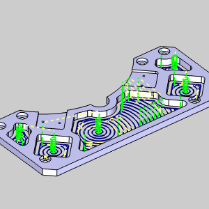
Advanced Pocket - Adaptive - Ramp at Drill Positions
When utilizing the Adaptive pattern of the Mill 2 Axis Pocket operation, many users have begun to realize how they can control the shape of the toolpath by adjusting the start locations with the Drill Tip Positions. The downside to using Drill Tip Positions is that the software assumes there is a drilled hole at these positions, so the tool would always plunge. To give the users the control to adjust the start locations when using the Drill Tip Position points, we have added a Ramp at Drill Positions checkbox so that ramping at this position is now possible! This is only available for the Adaptive pattern.
|
When using an advanced pocket with a ramp entry, you may want to enter from previously drilled positions in the stock. |
|
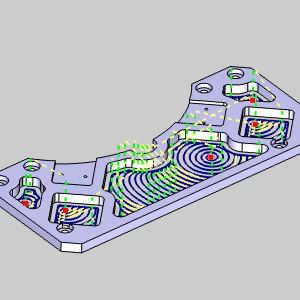
In the past, selecting drill tip positions overrode the ramp entry method and applied a basic plunge entry. |
|
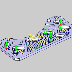
By selecting Ramp at Drill Positions, you can easily ensure a ramp is still applied to the selected drill tip positions! |
Advanced Pocket - Smoothing
The same powerful smoothing options which have been available for our Advanced Roughing operation are now available for the Offset Pocket Out and Offset Pocket In patterns of the Advanced Pocket!
Clicking on the Smoothing button in the Parameters page will launch the Smoothing dialog, allowing you access to.
- Smooth Corners - to create fillets in the sharp corners
of the toolpath.
- Smooth Links - to smooth the links within a group.
- Smooth Final Contour - to create fillets in the sharp corners of outer contours.
- Ignore Small Contour - box to remove small pockets and segments which
are not necessary to machine.
- Remove Corner Pegs - to add extra
tool movement in corners, removing the rest material with:
- Line-Arc-Line - removes the corner pegs with an arc between two lines.
- Arc - removes the corner pegs with a single looping arc motion.
- Line - removes the corner pegs by moving away from, and back to the toolpath with a straight line.
- Line-Arc-Line - removes the corner pegs with an arc between two lines.
Mill 3 Axis Pro
Dynamic Holder Checking
The power of Dynamic Holder Checking has now been extended to many of the finishing operations! When using a short tool, it can be impossible to get to the necessary depth without causing a collision between the machining surface and the holder. In the past, you could use gouge checking options which check for gouges once the toolpath has been calculated, and then trim and relink the toolpath. Now, this option checks for gouges in the machining surface during the toolpath calculation and offsets the toolpath as necessary!
-
Advanced Z Level Finish
-
Advanced Planar
-
Equidistant
-
Project Curves
-
Flatlands
-
Pencil
| Original toolpath | ||
|
||
| Gouge Check: Retract | Dynamic Holder Checking | Collision Safe Area Only |
|
|
|
Start Location Control
This latest version brings the power of start location selection to the Advanced Rough, Equidistant, and Pencil operations. When programming a part, the more control you have, the better. That's why it was such a huge hit when we offered control over exactly where your Advanced Z Level operations starts. Now this same control is available in these other operations! Simply select your start point from the graphics area, or even enter it manually!
| Undesirable Start Location | Adjusted Start Location |
|
|
This works for the regions as well! Whereas the above example has only one start point, operations with multiple regions have multiple start points as in the examples below. Notice the original part with toolpath and notice the start points being affected with the selected start points.
|
|
Equidistant - Corner Slowdown
The Equidistant operation now allows you to slow the feedrate when moving into corners. When programming speeds and feeds many things need to be taken into consideration, especially ensuring the tool does not engage too much material at the same time since this can easily break a tool. When moving around a part, additional stock is always encountered in the corners, so a corner slowdown option has always been a hugely popular customer request. When we brought that power to many of our Mill 2 Axis features it was an enormous hit! Now, we offer that same control in one of the most powerful 3 Axis operations ever: The Equidistant operation!

Advanced Rough - Stock Has Undercuts
The Advanced Rough operation now has the Stock Has Undercuts option to allow you to ignore areas in the stock that are undercut. One of the main advantages of the Advanced Rough has always been its ability to focus only on the stock and avoid air cutting when the top of the stock is not flat. In the past though, the operation did not have the ability to recognize undercut areas of the stock. This meant even a small lip at the top of a stock form would cause toolpath to continue down past the lip and waste time cutting air. This new option allows these areas to be recognized and ignored, saving more time than ever before possible, and even offers an Axial Shift option to control how much is trimmed!
Advanced Rough - Adaptive Roughing - Ramp at Drill Positions
When utilizing the Adaptive pattern of the Mill 3 Axis Advanced Rough operation, many users have begun to realize how they can control the shape of the toolpath by adjusting the start locations with the Drill Tip Positions. The downside to using Drill Tip Positions is that the software assumes there is a drilled hole at these positions, so the tool would always plunge. To give the users the control to adjust the start locations when using the Drill Tip Position points, we have added a Ramp at Drill Positions checkbox so that ramping at this position is now possible! This is only available for the Adaptive pattern.
|
|
When using an advanced pocket with a ramp entry, you may want to enter from previously drilled positions in the stock. |
|
|
In the past, selecting drill tip positions overrode the ramp entry method and applied a basic plunge entry. |
|
|
By selecting Ramp at Drill Positions, you can easily ensure a ramp is still applied to the selected drill tip positions! |
Advanced Z Level Finish - Retract clearance for 3-Axis undercuts
A new feature has been added to the Advanced Z Level Finish allowing you to do undercuts with a radial clearance added for the tool. When using tools like a t-cutter to preform undercuts, making sure the tool doesn't contact the part when entering and exiting the cuts is extremely important. In this version, simply add a Retract Clearance value in the Options page to provide additional clearance as necessary.
Advanced Z Level Finish - Spiral Pitch Control
New controls in the Parameters page of the Advanced Z Level Finish allow you to set an angle to the Spiral method rather than just a depth of cut. Applying the Spiral method to the Advanced Z Level Finish has always been a great way to eliminate linking moves to get the best possible finish. In the past though, the only way to specify how tight of a spiral to use was by setting the Depth of Cut. Now, by selecting Spiral Angle in the Depth of Cut group, you can specify an Angle and a Maximum Depth to use, giving you just a little more control when perfecting your toolpath!
| Define the Angle | Set a Maximum Depth |
|
|
Note: The Maximum Depth ensures a full cut at each Maximum Depth increment. In the images above, the first is given a maximum depth greater than the part depth, while the second is given a maximum depth of half the part depth.
Mill 3 Axis Premium
Deburring
Chamfer Tool
Last year we introduced the new Deburring toolpath which supported fully automated deburring processes for 3, 4, and 5 axis machining by practically just selecting the model and hitting compute. In the initial release, only spherical tools could be used, such as ball end mills, lollipops, and tapered ball end mills. Of course, the biggest request was making it work with Chamfer tools, and now in this release you absolutely can!
-
Endmill Rough
-
Endmill Finish
-
Tapered
-
Lollipop
-
Chamfer Mill
Containment Body
Now you can automatically specify which areas to deburr by selecting a containment body! While the Deburring operation has always offered ways to specify the area to focus on by allowing selection of specific edges, check surfaces to avoid, and limiting the area by height, deburring only specific areas meant a lot of geometry selections and even adjustment of the operation settings. Now, hitting exactly what needs to be hit has never been easier. Simply select a solid, or solids from the graphics area and only the area inside of these solids will have the Deburring toolpath applied!
Allow Asymmetric Chamfer
A new option has been added to the Advanced auto edge detection dialog of the Deburring operation to allow you to cut asymmetric chamfers when using the fixed tool contact point option in a 3 or 4 Axis setup. Symmetric chamfer geometry is defined by half the edge angle, and in the past edge angles beyond this range were ignored. By allowing asymmetric chamfers you're able to machine more edges with different angles and orientations to hit more edges automatically than ever before.
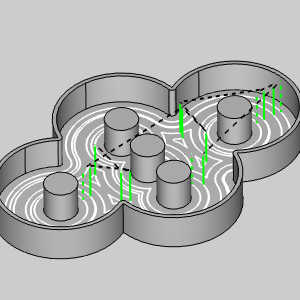
Fixed Tool Contact Point on Cone / Cylinder
The new Fixed tool contact point on cone/cylinder option enables you to specify where the edges should contact the cutting edge of the tool. In previous versions fixed contact point options were not available for the deburring operation. With option you can determine exactly where the tool is positioned with a fixed contact point as specified with a value of 0 to set it as the lowest point, up to a value of 1 to set it at the highest point of the cone/cylinder. This option allows you to create an incredibly uniform chamfer but do note to create a uniform chamfer the tool is not tilted, and toolpath will be trimmed instead of tilted to avoid areas of collision.
Spiralize Closed Contours
When using multiple cuts along edges, the new Spiralize closed contours option allows you to spiral to the additional cuts instead of using linking moves. In some cases, multiple cuts need to be applied to edges, and in the past those separate cuts were connected by linking moves which can result in visible marks on the final product. To eliminate this issue, the new Spiralize closed contours uses a spiral move along the contour to smooth the transition into the next cut. This helps create smoother machine movements and a cleaner result!
Flow direction
New options have been added to the Flow directions of the Flowline toolpath which allow you to choose between U - direction and V - direction. In the past, the only Flow directions available were Long side and Short side, which were the same directions, but selectable only by which was longer/shorter. In some cases, users wanted the U or V direction to have priority regardless of its length. In that scenario the only option was choosing one and seeing if that was the desired result. With these new options, you have everything you need to specify either the U or V direction regardless of length, or length regardless of direction.

Steep Shallow - Independent Cutting Methods
The powerful Steep Shallow operation has gotten even more powerful with the ability to control the Cut Direction for the Steep and Shallow aspects of the operation independently. The Steep Shallow operation is arguably the most versatile operation in the 'toolbox', but until now, could only be controlled by a single cut direction: Zig with Climb or Conventional milling, or a Zig Zag. This choice would apply to the overall toolpath on both the steep, and shallow areas. Now, by selecting the Independent Methods check box in the Patterns page, you can assign one direction for the steep areas and one for the shallow areas, making one of the most versatile toolpaths even more versatile.
Mill 4 Axis Standard
4 Axis Rotary - Maximum/Exact angle step
New options in the Links page of the 4 Axis Rotary operation allow you to set a maximum angle step for the rapid moves of the operation. While the 4 Axis Rotary toolpath has always had options to control the links of the toolpath, control of the rapids, besides the height of those rapids, has not been available. With this latest version, you can specify an angle step which can be treated as a maximum angle with the rapids divided into equal parts or used an exact value.

|
|
| Maximum divides evenly |
Exact uses the value and a remainder |
|
|
Mill 4 Axis Pro
Conical Machining
A brand-new option has been added to the 4 Axis Advanced Rough and 4 Axis Advanced Finish operations which perfectly applies the toolpath to conical shapes! Conical machining can be tricky, and when we came out with our 4 Axis Advanced Rough and 4 Axis Advanced Finish operations it helped a lot in the machining of those shapes, but the toolpath wasn't specialized for those shapes, and there were still some drawbacks. Everything from the step downs to the limits, is designed for cylindrical shapes. That meant conical floors would have steps, and air cutting on the smaller end was impossible to remove with radial limits. These issues are now a thing of the past with the new Conical Machining option. Simply select the check box on the Patterns page, set the Cone Angle and now the entire toolpath is designed for that exact shape! New options on the limits page even allow you to set conical Start and End values. giving you the control to machine exactly what you need with ease!
New Boundary option
The 4 Axis Advanced Rough and Advanced Finish operations are continuing to mature and now offer the ability to select a 3D containment boundary to define more specific areas of the model to cut. The familiar functionality you are used to utilizing for Mill 3 Axis operations is now introduced for 4 axis machining!
Force Floor Cuts
The Force Floor Cuts option, once only available when using the Adaptive Depth Step option, is now available when using Constant Depth Step as well! When using the 4 Axis Advanced Rough and Finish operations, this option provides an easy way to make sure the floors are cut to the final depth without having to make sure your depth of cut hits those floors. Although the Adaptive Depth Step was designed to adjust the depth to hit floors, you still had to set parameters to dictate the allowable depth of cut and occasionally these parameters wouldn't allow cuts on the floor without the Force Floor Cuts option. In the past, the Constant Depth Step option had no option to ensure floors were cut, but now this powerful option is available for whichever depth option you choose!
|
|
|
|
|
Side Shift
The 4 Axis Advanced Rough operation now allows you to add a Side Shift value to your selected Cut Pattern! To get the most effective cuts possible it's ideal to have the tool offset from the axis of rotation to achieve the best tool engagement. In the past the option to shift the tool to the side of the rotary axis was only available in the 4 Axis Rotary operation, but now this option comes to the 4 Axis Advanced Rough to give an extra edge to an already powerful toolpath.
Tilted with fixed angle to surface normal
Another tilting option is added to the arsenal of the Surface toolpath types with the new Tilted with fixed angle to surface normal option. The proper tool tilt is important in multiaxis machining, and while we have many options to choose from, including staying fixed to the surface normal, in the past you have not be able to adjust the tilt based on the surface normal. In this version though, you can do just that! Simply select the option, choose your reference surface and set your angles.

New Considered profile section options
New options have been added to allow you to determine the shape being considered when defining the point of contact on the tool. Recently we added an option to specify a contact point to use when tilting relative to cutting direction. Originally this option only allowed you to set the contact point on the curved sections of the tool by specifying a value between 0 and 1. With the following new options you're able to define the profile where the contact point should be placed:
-
Full profile - The entire profile from the tip to the end of the flute.
-
Curved Profile - The entire profile with a convex curvature.
-
Flatness Diameter - The flat side of the tool.
-
Tip Radius - The tool tip.
-
Convex tip - The entire convex area including the tool tip.
-
Cone - The cone face.
-
Cylinder - The cylindrical face.
-
Barrel - The barrel face.
For the Wireframe and all Surface toolpaths, this lets you position the contact point not only on the curved sections of the profile but also on the entire profile including the cylindrical and conical sections!

Tilt rate for automatic tilting
A new Max. tilt rate option has been added to the Params. for automatic tilting dialog of the Gouge check page allowing you to control the max angle change per unit of travel for the Wireframe and all Surface toolpaths. While we've had ways to define the tilt angle and its allowable range, we've never had an option to control how quickly it's able to tilt within that defined range. With the new Max. tilt rate option, you can specify an angle per mm value to avoid abrupt changes in the tilt to lower accelerations and create smooth machine movements. In the images below you'll see the tool axis shown in red at each toolpath point in an isometric and top view. Notice when using the Max. tilt rate option, you can add a value allowing you to help smooth the transition of the tool.

Optimized automatic arcs
When using the Surface toolpath types with automatic arcs and blended spline links, new options are available for the Lead-in and Lead-outs called Align towards previous cut and Align towards next cut. These options allow you to specify a value between 0 and 1 to control how the automatic arcs end which, in turn, controls the blended spline links. By default, the automatic arcs point away from the surface. This forces the blend spline links into large loops. These new options allow you to force the automatic arcs to continue their shape until they point towards the next cut. This allows the blend spline links to stay much closer to the surface being machined which can greatly reduce cycle times!

Mill 5 Axis Standard
5 Axis Undercuts
The Undercut option in the Options page of the Advanced Z Level Finish now allows you to do undercutting when the operation is set to 5 Axis in the Tool Axis Control page. While the undercutting option has been a huge help when using undercutting tools in a 3 Axis operation, the undercut option has so far been unavailable when setting the operation to 5 Axis. Now, when set to 5 Axis, you can use Undercut with spherical tools by simply selecting one of the Checks on the Gouge Check page, and setting the Strategy to Tilt tool! You can even set an Extend undercut area value to have full control over exactly how much is machined!
Wireframe - Minimum distance
The Surface quality group of the Wireframe operation now offers a Minimum distance option with a Deviation factor. In the past the only Surface quality options were Cut tolerance and a Maximum distance option. This allowed you to have some control over the distance between the toolpath points by setting a maximum allowable distance between them, but that was it. In this latest release, with the addition of the Minimum distance option and Deviation factor value, you have everything you need to control the distance between toolpath points.

Mill 5 Axis Pro
Multiaxis Machining - Rest Finishing
Adding to the power of Multiaxis Machining operation is the new Rest Finishing machining pattern which allows you to concentrate toolpath on areas previous tool and machining patterns could not reach. Rest finishing has always been a huge help for each operation it was introduced to. Being able to tear through material quickly with the largest tool possible is only helpful if you can come back and focus on the missed nooks and crannies with a smaller tool. Now, you can do just that with Multiaxis Machining! Use a large tool with the Wall, and Floor Finishing, and then come back with the new Rest Finishing and a smaller tool to get machining time down further than ever!
-
3D Containment
The 3D containment dialog in the Multiaxis Machining operation has been updated to allow the user to select Auto and choose the previous operations the Rest finishing should be applied to.
Multiaxis Machining - Fixture Geometry
A new option has been added to the Roughing pattern of the Multiaxis Machining operation allowing you to specify fixture geometry so it can be avoided during toolpath calculation. In the past, avoiding fixtures meant using the 3d containment option to avoid fixtures. This meant you either had to draw a boundary to use, or move around selecting all the necessary surface edges to define your boundary. This worked of course but having a rigidly defined boundary to contain toolpath isn't nearly as good as simply selecting the item to avoid! And that's exactly how easy it is in this latest version! Simply select the feature and the toolpath calculates the best route around the fixture!
Multiaxis Machining - Interpolation tilt angles
The new Interpolation tilt angles option in the Multiaxis Roughing pattern gives you the ability to set an angle step for the rapid and feed moves of your retract links! While the Retracts dialog of the links page has always given you the ability to set the distances of your rapids, entries, exits, and air moves, never have you been able to control how the retract links were defined. Simply set the angle step values and you can control the exact machine angle between toolpath points.

Mill 5 Axis Premium
Advanced Rough - New Link options for Automatic 3+2 Roughing
A new Between Orientation Change group has been added to the Links page of the Advanced Rough operation. Available when using the Automatic 3+2(5Axis) option in the Tool Axis Control page, this group allows you to select between the new Blend Spline and the Full Retract linking options to control how the moves between tool orientations occur. In previous versions, there was no way to control how the tool transitioned between these orientation changes, which could cause abrupt orientation changes in certain situations. Now, just select the Blend Spline option, which will cause the tool to retract from one orientation and begin transitioning to the next orientation, arriving at the proper tool angle just before the -Z moves in the new orientation.
| Blend Spline | Full Retract |
|
|
|
|
|
|
| The new Blend Spline option provides a smooth transition between orientations. | In the past, abrupt changes in orientation could be an issue as in the above instance |
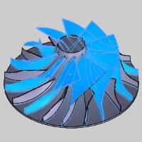
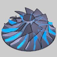
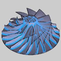
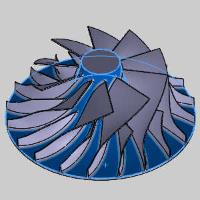
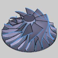
Multiblade - Fillets
In this latest version Fillets are selected separately from the Blades, splitter geometry to improve toolpath quality and produce better roughing paths with bullnose and flat tools. In previous versions, defining your geometry forced you to define the Hub as one group of geometry, and then Blades, splitter, fillets as the other group. Since then, it's been found that by defining blades/splitters, fillets, and the hub separately we're able to increase the quality of the toolpath, so that's exactly what we've done! Just pick the Blades and splitters together, pick the fillets, and pick the hub, to complete your part definition and squeeze even more precision out of your toolpath!
| Blades | Splitters | Fillets | Hub | Shroud |
|
|
|
|
|
Simulation
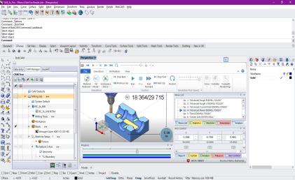
Launch Simulation in a Separate Window
An option in the System > CAM page of the Settings dialog now gives you the ability to launch the simulation as a separate, independent window! When working on a computer, screen space is always at a premium and sizing the various windows in the application to allow easy access to all their content is standard. In the past, once you opened the simulation in the graphics area, you could find yourself resizing many of those windows to give the simulation and its windows as much room as possible. Now, with the Simulation Window options, simply select Separate Window and the simulation will launch as its very own window giving you tons of elbow room to use the simulation to its full potential without having to adjust the size of the graphics area.
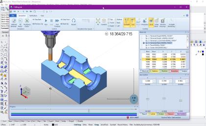
Toolpath Analysis options: Custom number of decimals
The number of decimals for applicable toolpath analysis items can now be adjusted to match the decimals set for the Move List. In the past, the number of decimals for these items was hard coded and could not be changed. Now, simply set the number of decimals for the move list items and the following Toolpath Analysis options will match:
-
Axis Value
-
Axis Value Change
-
Axis Speed
-
B+C Axis Speeds
-
Orientation Change
-
Axis Pole

Posting
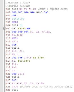
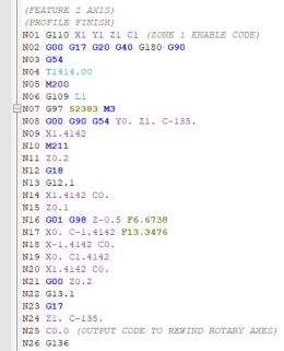
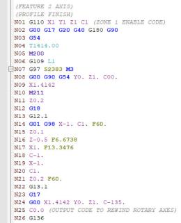
Polar Interpolation : Output forcing the start angle at C0
A new posting question has been added to work with controllers which require the C axis to be at 0 prior to polar interpolation being called. Originally we offered a way to output relative to the start angle with post question 3528. Polar coordinates relative to start angle?. This post question would handle the standard cases along with needing the output relative to the start angle. That post question has now been deprecated in favor of a question which handles each of those cases, along with the case of a controller needing C0 positioning prior to the polar interpolation call!
3529. Polar coordinates mode (0: Default mode, 1: Relative to start angle, 2: Start at C=0)?
-
Outputs are as is for polar coordinates.
This is like setting the now deprecated post question 3528. Polar coordinates relative to start angle? to no -
Outputs are calculated relative to the start angle.
This is like setting the above mentioned post question to yes. -
Outputs are forced to start at C=0 and first point is calculated after starting at C0.
This new option also comes with an associated post question for controlling the feedrate of the new calculated position: 3597. Feedrate value for feed move (for Option 2 in 3529.)? 60.0
|
Cutting this two inch square centered in the stock will give us the following output depending on the setting. |
||
|
||
| 0 | 1 | 2 |
|
|
|
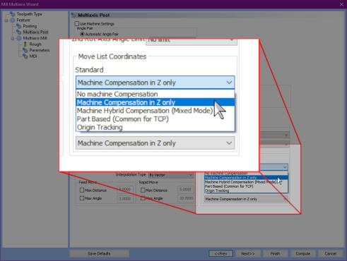
Arc break rule based on posting mode
A new post question has been added to allow arcs to be output for specified posting modes while being broken for others. Outputting arcs in your code can be helpful, but in certain posting modes, controllers won’t accept arc output. While we’ve offered ways to break arcs in the output, it could be frustrating having a small portion of the code dictate whether arcs should be output for the whole of the program. This issue has been solved with the addition of the new post question:
556. Arc break rule based on posting mode?
If post question 550. Break arc segments into lines? Is set to ‘n’, this newest post question allows you to specify for which of the posting scenarios seen below, if any, arcs should be broken for. The valid answers to the posting questions are :
|
|
Combinations of rules can be used by adding the values of several options together. For instance, using a value of 3 will be the same as using values 1 and 2 so arcs are not output while using TCP or Machine Comp in Z only. With this new post question, you should be able to utilize arcs wherever possible, while avoiding them where necessary.
Prefix Specific to thread_g33_feedrate
A new prefix block has been added to the Lathe and Mill Turn posts allowing a prefix to be specified for the lathe threading variable thread_g33_feedrate which does not affect that of other feedrates. In the past, prefix block 1707. Symbol for IPM feedrate? was used to control the prefix, but after encountering controllers which require lathe threading feedrate to be specified with a unique prefix. As a result prefix block 1708. Symbol for UPR feedrate (thread_g33_feedrate)? has been created, enabling lathe thread feeds to be called with a unique prefix as needed! Notice in the image below, the lathe thread operation was updated to us a prefix of "L" for its feedrate without affecting the other feedrates.
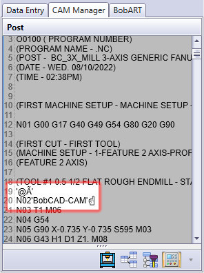
Character Output
A new posting variable allow you to output any characters in the posted code by specifying its ascii/Unicode value. Occasionally, we get a request for a particular character to be output in the posted code. To cover all possible cases moving forward we've created the posting variable charout_xx.
The values following charout_ support 2 variations:
Decimal value – charout_64
Hexidecimal – charout_0x261D
It is important to understand this variable does interact with post question 228. Support Unicode Output? y/n so if your post processor is set to only support ASCII characters, you cannot output characters from the higher Unicode set of characters.
As an example, by adding the line below to the post under the file header section:
charout_39, charout_64, charout_195, charout_0x27
n,charout_39, charout_66, charout_111, charout_98, charout_67, charout_65, charout_68, charout_0x2D, charout_67, charout_65, charout_77 , charout_39, charout_0x261D
We get the following result depending on the setting of question 228.
| 228. Support Unicode Output? y | 228. Support Unicode Output? n |
|

|
To learn more about unicode characters, click the following link to open the wikipedia article: List_of_Unicode_characters
Enhancements
CAM
Mill
Mill Express
Advanced Pocket - Arc Fit Links
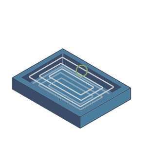
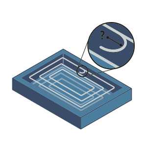
New optimization is used to output arcs when posting Advanced Pocket operations using the S-Link option in the Links page. When the choice is outputting lines or arcs on your machine, the choice is clear. When arcs are output, it requires less code and makes for smoother machine moves. In this version, when you're using S-Links with the Offset Pocket Out, Offset Pocket In, or the Morph Spiral pattern, arcs are automatically output in the code to help for smoother machine moves and reduced code output of 50% or more!
| Previous S-Link Toolpath Points (Lines) | New S-Link Toolpath Points (Arcs) |
|
|
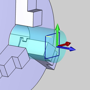
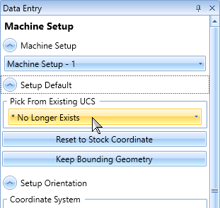
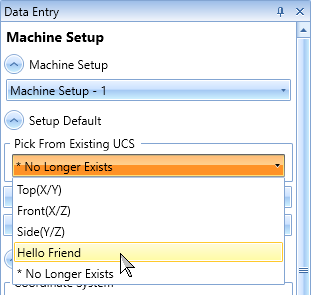
Update to UCS Selection
In past versions, when setting a Machine Setup or an Index System from an existing UCS, the coordinate system would update after choosing the UCS from the drop down. However, when editing later, it sometimes created confusion because when they went back to the dialog the UCS they had picked was no longer shown as selected in the drop down. We have made some adjustments to the drop downs for UCS selection in the Machine Setup and Index System to help clarify that choosing a UCS is an action to update the coordinate system and not associating the index system to a UCS entity. Now if the UCS still exists and is in the same position, the UCS used will remain shown as the selected item in the combobox. If the coordinate system that was used when creating the Machine Setup or Index System no longer exists in the UCS Manager, it will display * No Longer Exists.
Mill 3 Axis Standard
Adaptive Roughing / Adaptive Facing - Over-machining
To make sure material is cut away as cleanly as possible, the Adaptive Roughing pattern has been improved to eliminate stand-ups. In the past, the Adaptive Roughing would end by cutting off a tiny column of material which was untouched by the operation until the final move. While this piece of material was usually cut away, a tiny burr could sometimes be left on the face of the stock. In this latest version the algorithm has been updated to ensure the material is finished evenly.

Mill 4 Axis Pro
4 Axis Advanced Finish - Lead in/out for finishing
Lead-in and Lead-out movements for your 4 Axis Advanced Finish operation are now automatically placed intelligently and are performed using 3-axis movements. In the past the lead moves could be placed in positions which were less than ideal. These leads were also output using 4 axis movements. In this release, we've adjusted the algorithm to ensure leads are placed on the most convex points inside the contour of closed pocket areas, or at the center point in straight regions to improve the consistency and accessibility of your start points. The connection between the start points is also the shortest distance according to those criteria. On top of this, the moves are now output without rotary axis movement to simplify NC programs and reduces additional rotational movements.
4 Axis Advanced Rough - Spiral
When using the Offset and Spiral cut pattern for the 4 Axis Advanced Rough the tool now starts in the middle of the pocket for barbell-style geometries. In previous versions, all areas would be cut the same, starting from one side and moving to the other. To create the most effective path, areas like that shown begin in the middle and work out.
4 Axis Advanced Rough and 4 Axis Advanced Finish - Machining area enhancements
In this version the depths cuts calculation of the 4 Axis Rotary operations has been improved to work easily with the radial limits. When adding radial limits in previous versions, the first depth cut would be applied directly at the outer limit, while the final depth cut exceeding the limit would simply be removed. In this release, the first depth cut is applied one depth below the outer limit and a final depth is created at the radial start. This helps to ensure you can get exactly what you want without having to fudge the radial limit values.
|
|
| Old | New |
|
|
Turn Milling - Improve cutting radius calculation
The depth step of your Turn Mill operations is now calculated from the outside in to ensure the first cut radius is always the depth step, and is less than the outer-most part or stock radius, whichever is greater. In previous versions, the depth was calculated from the center of rotation which could be confusing when trying to set the depths based on the part or stock. In this version depths are easily calculated inward from the outer most portion of the stock/part.
Turn Milling - Orthogonal leads improvement
The orthogonal leads in Turn Mill operations have been updated to reduces air cuts and maintain a consistent 45-degree angle which can help to reduce cycle times. By beginning each cut the feed distance plus the depth step used much of the wasted air cutting in previous versions is eliminated.
Mill 5 Axis Premium
Port Machining 4 Axis Enhancement
The Port Machining operation has been updated to provide much better results when output as a 4 Axis operation. The Port Machining operation was intelligently designed to give excellent results with 5 Axis output, but in previous versions limiting the output to 4 Axis could drastically limit the coverage depending on the selected geometry. In this latest release, the algorithm has been improved to greatly increase the machinable area with 4 Axis output.
