In this Topic Show
Simulation is an extremely powerful tool for viewing and analyzing the machining process. This tutorial reviews the main areas of the simulation interface and its major features to get you started successfully utilizing the power of toolpath simulation in BobCAD-CAM.
There are two levels of simulation in BobCAD-CAM: Standard and Pro.
This provides a full-featured simulation engine that displays the stock, workpiece, and tool.
This provides the same functionality as the Standard Simulation and adds the ability to define a virtual machine so you can view the complete machine motion and even perform collision checking between machine components.
To open simulation, do one of the following:
 Simulation.
.
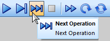
The Control toolbar is used to navigate the program simulation. This includes the run, stop, next operation, and restart buttons. The speed slider controls how fast or slow the simulation runs, and the mode determines how the tool movement displays (real-time feedrate, constant speed, or move list positions).
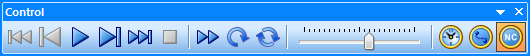
TIP: You can use tool tips to help familiarize yourself with the toolbar buttons. To use tool tips, point to the button and wait a moment for the tool tip to display the button description.
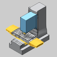
The Focus toolbar determines what element is the focus of the simulation. With Tool Focus, the tool remains fixed and the workpiece moves. With Workpiece focus, the workpiece remains fixed and the tool moves. With Machine Focus (available only for Machine Simulation Pro), the full virtual machine and its movement display in addition to the stock and workpiece.

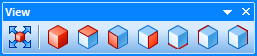
The Views toolbar provides all of the standard viewing orientations and a fit to screen button.
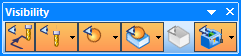
The Visibility toolbar allows you to select what elements display during simulation and their visibility status: visible, transparent, or hidden. You can control the visibility of the toolpath, tool, workpiece, stock, and the machine housing (Pro Simulation only).
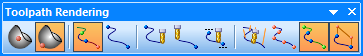
The Toolpath Rendering toolbar allow you to determine how the toolpath displays and what parts of the toolpath display. This includes displaying all operations, only the current operation, toolpath points, tool vectors, and whether or not lead and link moves display. You can also have the toolpath display only in areas the tool has already cut, hasn't cut, or a small segment before and after the current tool position.
The Settings toolbar provides the Simulation Properties and Hot Keys (keyboard shortcuts) so you can customize the simulation to your preferences. Note that you can also export a functional presentation of your simulation to share with clients or employees.

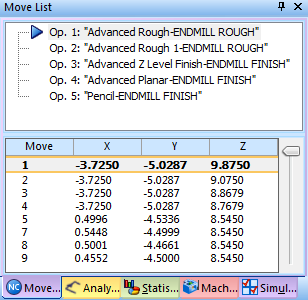
The ![]() Move List contains a list of all operations
and the tool moves for each operation. You can click an operation to go
directly to that part of the program simulation. You can also drag the
slider to go forward or backward in the simulation.
Move List contains a list of all operations
and the tool moves for each operation. You can click an operation to go
directly to that part of the program simulation. You can also drag the
slider to go forward or backward in the simulation.
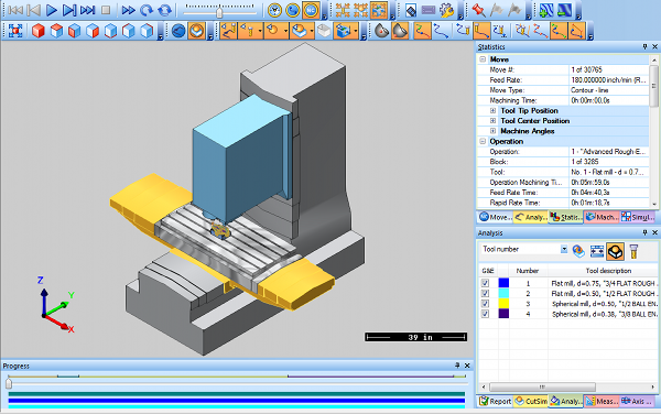
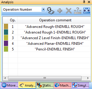
The ![]() Toolpath Analysis allows you to apply a coloring
scheme to the toolpath. For example, you can display the toolpath for
each operation or each tool in a different color. You can also select
a scheme that applies colors to the toolpath based on a specific type
of tool movement or change in movement. The colors can be fully customized.
Toolpath Analysis allows you to apply a coloring
scheme to the toolpath. For example, you can display the toolpath for
each operation or each tool in a different color. You can also select
a scheme that applies colors to the toolpath based on a specific type
of tool movement or change in movement. The colors can be fully customized.
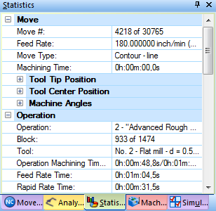
The ![]() Statistics provide important information about
the current move, operation, or all operations, such as the feedrate and
cycle time.
Statistics provide important information about
the current move, operation, or all operations, such as the feedrate and
cycle time.
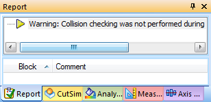
The ![]() Report provides useful information about collisions
that occur during the machining process, for example, a warning that manual
position changes were not collision checked.
Report provides useful information about collisions
that occur during the machining process, for example, a warning that manual
position changes were not collision checked.
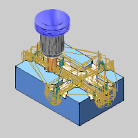
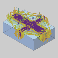
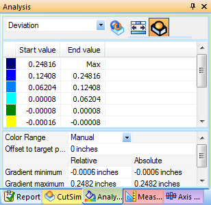
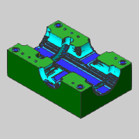
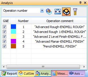
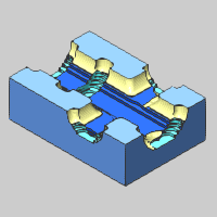
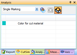
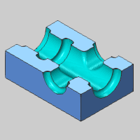
The ![]() Stock Analysis allows you to apply a coloring
scheme to the stock model. For example, the cut stock material can display
based on the operation number, tool number, or other criteria such as
height change, angle change, or toolpath length. You can also perform
deviation analysis to visualize the rest material.
Stock Analysis allows you to apply a coloring
scheme to the stock model. For example, the cut stock material can display
based on the operation number, tool number, or other criteria such as
height change, angle change, or toolpath length. You can also perform
deviation analysis to visualize the rest material.
The Deviation analysis allows you to compare the cut stock model to the target workpiece. You can set the range, gradients, number of colors, and even customize the colors used.
The Operation Number analysis displays all cut stock material with a separate color for each operation.
The Single Marking analysis displays all cut stock material using a single color.
To close the simulation window, do one of the following:
 Exit Simulation.
.
 in the upper-right corner of the simulation
window.
in the upper-right corner of the simulation
window.
Congratulations! You have completed the simulation overview tutorial. More usage examples of simulation are provided in the Getting Started CAM tutorials for each module. You can also view the BobCAD-CAM Help System.
After simulating a finished program, the next step in the process is to generate the NC program. To learn more, view Getting Started with Posting.