In this Topic Show
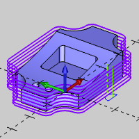
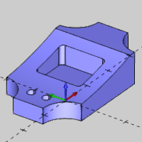
This tutorial explains how to create the machining program for the Mill 3 Axis Standard demonstration file. The process includes roughing and finishing the outer profile, drilling the holes, and then roughing and finishing the pocket. Next a 3 Axis feature with two planar operations is used to rough and finish the top of the part. The last feature is created to engrave text into the model before simulating the program to confirm the results.
This tutorial highlights the following functionality of the BobCAD-CAM software:
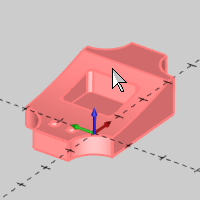
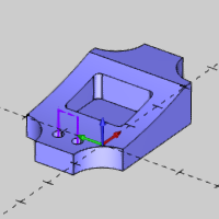
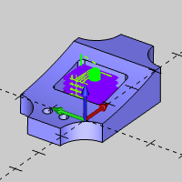
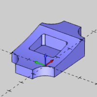
The first step is to open the finished Mill 3 Axis Standard CAD model from the Demo Files folder, and then use Save As to rename the file. It is good practice to properly name your files and save them often.
1 In the File menu, click Open.
2 Navigate to C:\BobCAD-CAM Data\BobCAD-CAM V28\Examples\Demo Files, and select Mill 3 Axis Standard CAD.bbcd.
3 Click Open.
4 In the File menu, click Save As.
Select or create a new folder to save to, or just use the Demo Files folder.
5 Change the File Name to Mill 3 Axis Standard CAM, and click Save.
The process of creating a CAM Job in BobCAD-CAM includes selecting the type of job and machine. You can then go directly to defining the stock geometry.
1 To create a new CAM Job, do one of the following:
In the Modules menu, click New CAM Job.
In the ![]() CAM Tree, right-click
CAM Tree, right-click ![]() CAM
Defaults, and click New
Job.
CAM
Defaults, and click New
Job.
2 Under Job Type, select Milling.
3 Under Machine, select BC_3X_Mill.
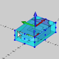
4 Click Stock Wizard.
When you start the stock wizard from the Machining Job dialog box, the Workpiece dialog box displays before the stock wizard. This is used to assign the geometry that we want to use as the workpiece when we simulate the program.
1 Under Define Workpiece, click Pick Solid Model.
2 Click to select the model in the Workspace.

3 Click
![]() to confirm the selection.
to confirm the selection.
4 Click
 to go to the Stock Wizard.
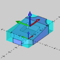
The Stock Wizard is a powerful stock creation tool which can automatically detect geometry in the Workspace to speed up stock creation.
1 Under
Stock Type, with Rectangular
selected, click .
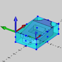
The default setting, Auto from Workspace, automatically creates stock geometry based on the CAD model.
2 Now we use the Enter method to update the automatically created stock size.
Under Size, click Enter, and update the parameters:
Length (X) = 4.125
Width (Y) = 2.750
Height (Z) = 1.250
3 Click
.
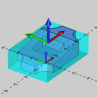
The Machine Setup is an important part of creating CAM Jobs in BobCAD-CAM. This includes setting the work offset number, clearance plane, and machining origin for each setup that you need on the physical machine.
1 In the Machine Setup under Origin, click Origin.
Select the machining origin at the top corner of the stock.
NOTE: This step defines the machining origin (work offset) location for the machining features that you create. The machining origin is independent of the CAD origin, and should be placed in the same location as the work offset location on the physical machine.
2 Click Work Offset. We use the default Work Offset # 1 (G54).
Notice the XYZ values. These are important to create proper simulation when using Machine Simulation Pro. These values shift the part location on the virtual machine (distance from virtual machine zero, which is the center of the top face of the table, to the Machine Setup location).
Update the values:
X = -2.000
Y = 1.250
Z = 3.000
Click OK.
3 Use the default Clearance Plane value of 1.000, and click OK.
The Milling Job is created with the defined stock and machine setup information.
4 In the File menu, click Save.
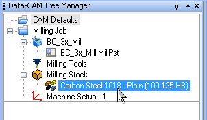
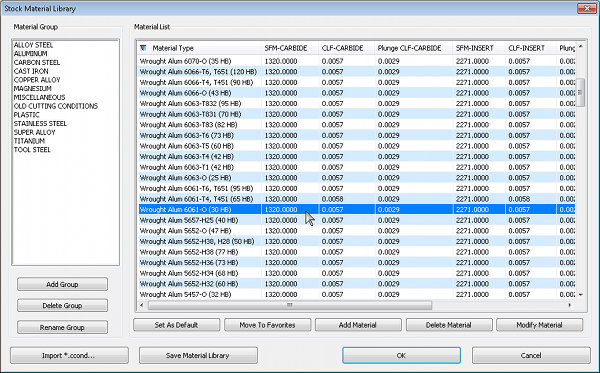
Selecting the appropriate stock material for the job determines the values used for automatic speeds and feeds calculations in the Milling Wizard. This information can be customized using the Stock Material Library.
1 In
the ![]() CAM Tree, right-click the current
CAM Tree, right-click the current ![]() Stock
Material, and click Edit.
Stock
Material, and click Edit.
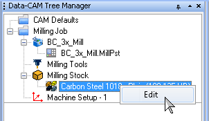
2 Under Material Group, select Aluminum.
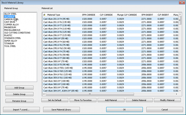
3 In the Material List, click Material Type to sort the list, and select Wrought Alum 6061-0, and click OK.
To begin creating our machining program, we add a 2 Axis feature with two profiling operations.
IMPORTANT: In this tutorial, we use many of the default settings and only update them as needed. If you want more information about particular settings, view the BobCAD-CAM Help System.
1 In
the ![]() CAM Tree,
right-click
CAM Tree,
right-click ![]() Stock,
and click Blank.
Stock,
and click Blank.
1 Right-click
![]() Machine Setup,
and click Mill 2 Axis.
Machine Setup,
and click Mill 2 Axis.
2 Click Select Geometry.
Right-click the lower surface edge, and click Constant Z.
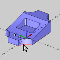
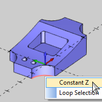
Press S to turn off the shaded view and easily confirm the selected loop. (Press S again to turn on the shaded view.)
3 Right-click anywhere in the Workspace, and click OK.
4 Click Next>>.
In this step, we use the model to select the Total Depth. Note that we don't select the Top of Feature, because it is already properly set to 0.000.
1 Next to Total Depth, click Pick Bottom.
2 Click the surface edge at the bottom of the model.
Notice that the Total Depth is automatically updated from the selection (1.000).
3 Click Next>>.
1 Under Template, confirm Profiling is selected.
This operation template contains two profiling operations, one rough and one finish, as shown in the Current Operations list.
2 Click Next>> twice to go to the Posting settings (we are not creating tabs).
1 Notice that Work Offset #1 (G54) is automatically selected as we defined in the Machine Setup.
2 Click Next>>.
1 For this operation we use the 0.500 inch diameter flat endmill that is automatically selected from using System Tool (Tool Label: 1/2 Flat Rough Endmill).
2 Click Next>>.
1 Under Patterns, select Contour Ramping.
Click Next>>.
2 We use the default Side Allowance of 0.015 to leave material for a finishing operation.
Under Depth, update the Depth of Cut value to 0.125.
No changes are made for the Leads, Corner Types, or Machine Sequence.
1 In
the tree under ![]() Profile
Finish, click
Profile
Finish, click![]() Finish.
Finish.
2 Again we use the automatically selected System Tool (Tool Label: 1/2 Flat Endmill - Standard).
1 In
the tree under ![]() Profile
Finish, click
Profile
Finish, click ![]() Leads.
Leads.
2 Under Lead-in, select Circular.
Notice that the Lead-out is automatically set to use the same settings because Same as Lead-in is selected.
We use the default settings for all remaining Profile Finish parameters.
1 At the bottom of the Mill 2 Axis Wizard, click Compute.
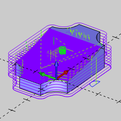
Press T to turn on the transparent view and make it easier to view the toolpath. Notice that the toolpath calculated inside of the model. (Press T again to turn off the transparent view.)
This is easily resolved next by modifying the start point direction.
Understanding how to modify the start point is an important part of creating 2 Axis features.
1 In the CAM Tree under Feature 2 Axis, click Default Chain Start Point.
This highlights the chain in the Workspace. The start point shows that the chain is counterclockwise, and the default compensation is System Compensation Left.
There are two options to update the start point. You can reverse the direction, or you can also modify the start point to any location.
2 Right-click Default Chain Start Point, and click Reverse Direction.
We can now compute the toolpath to correct it, but let's first move the start point to a better location.
3 Right-click Default Chain Start Point, and click Modify.
Click near the center of the surface edge as shown next.
TIP: While modifying the start point, you can just click near the start point (small cone) to reverse the direction.
4 Click
![]() to confirm the selection.
to confirm the selection.
5 Right-click
![]() Feature 2 Axis, and click Compute All Toolpath.
Feature 2 Axis, and click Compute All Toolpath.
1 Right-click Feature 2 Axis, and click Blank/Unblank Toolpath.
You can click each operation in the CAM Tree to highlight only that toolpath in the Workspace. The hidden toolpath displays in the Workspace until you click another tree item.
TIP: All feature items in the tree (Feature, Geometry, and Start Point) as well as the operation items highlight the corresponding feature information in the Workspace when you click them.
2 Next
to Feature 2 Axis, click  to collapse the feature.
This is helpful to reduce the need for scrolling through the CAM Tree as the number of features increases.
3 Press Ctrl+S to save the file.
Now we use the Mill Hole Wizard to machine the two holes in the model.
1 Right-click Machine Setup, and click Mill Drill Hole.
2 Click Select Geometry.
3 Select the cylindrical face of each hole.
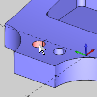
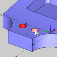
4 Click
![]() to confirm the selection.
to confirm the selection.
The Hole Diameter, Top of Feature, and Feature Depth is automatically set for the selected holes, because we selected cylindrical geometry.
5 Click Next>>.
Notice in the Feature settings under Hole Groups, the Top of Feature and Feature Depth are automatically set based on the geometry we selected.
For this example, we are drilling the holes before we have cleared the material above them. For this reason we update our Top of Feature value because the geometry we selected is below the stock material that is removed after the drilling operations.
6 Under Hole Groups, click the Top of Feature value (in the row of Group 1) to make it available for editing.
Type 0.000, press Tab to move to the Feature Depth value.
Type 1.000 and press Enter to update the Feature Depth.
Notice the feature preview updates in the Hole Groups preview window to show the new settings.
1 In the tree on the left, click Machining Strategy.
2 Under Template, select Ream.
This operation template adds one Center Drill, one Drill, and one Ream operation to the Current Operations list.
3 Click Next>> to update the tree with the new operations.
1 Click Next>> to go to the Center Drill tool settings.
2 Notice that System Tool is selected which automatically picks an appropriate tool from the Tool Library (after searching the Tool Crib).
We use the default Center Drill Parameters and System Tool again for the Drill operation.
3 In
the tree under ![]() Drill,
click
Drill,
click ![]() Parameters.
Parameters.
4 Under Cycle Type, click Peck.
We use the default settings for the Ream operation.
1 Click Compute.
2 Right-click Standard Feature Mill Hole, and click Blank/Unblank Toolpath.
3 Click
to collapse the feature.
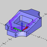
In this section, a Mill 2 Axis feature is created to rough and finish the pocket in the center of the model.
1 Right-click Machine Setup, and click Mill 2 Axis.
2 Click Select Geometry.
Click to select the bottom face of the pocket,
and click ![]() to confirm the selection.
to confirm the selection.
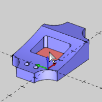
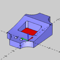
The software automatically extracts the edges of the selected surface to use for the feature.
3 Click Next>>.
1 Click Pick Bottom.
Click any edge at the bottom of the pocket.
The Total Depth value is updated to 0.750.
2 Click Next>>.
1 Under Template, select Pocketing.
This operation template contains one Pocket operation and one Profile Finish operation as shown in the Current Operations list.
2 Click Next>> to update the tree with the new operations.
1 Under
Pocket, click![]() Rough to go to the tool settings
for the operation.
Rough to go to the tool settings
for the operation.
2 Click Tool Crib.
3 Under Tool Category, click Endmill Rough, and click Add from Tool Library.
4 Click the column name Diameter to sort the tool list.
Select the 0.375 inch diameter flat endmill with the 0.875 inch flute length (Tool Label: 3/8 Flat Endmill - Standard).
Click OK.
5 Click OK in the Tool Crib.
Click Next>>.
1 Under Patterns, click Advanced Pocket.
Click to select the Adaptive Roughing check box.
NOTE: The Advanced Pocket pattern can be used for open or closed pocketing, and the Adaptive Roughing check box makes this a high-speed machining strategy.
2 Under Parameters, change the Stepover % value to 20.
Click Next>>.
3 Under Depth, click Multiple Steps.
In the Depth of Cut box, type 0.750/5 and press Tab.
Notice that the software automatically calculates the value to 0.150.
4 Click Next>>.
1 Select Ramp, and use the default Ramp Length and Angle of Approach values.
1 In
the tree under ![]() Profile
Finish, click
Profile
Finish, click![]() Finish.
Finish.
2 Click Tool Crib.
3 Under Tool Category, click Endmill Finish, and click Add From Tool Library.
4 Select the 0.125 inch diameter flat endmill with the 1.000 inch flute length (Tool Label: 1/8 Flat Endmill - Long).
Click OK.
5 Click OK in the Tool Crib.
1 In
the tree under ![]() Profile
Finish, click
Profile
Finish, click ![]() Leads.
Leads.
2 Under Lead-in, click Circular.
Under Line, change the Length value to 0.125.
Under Arc, change the Radius value to 0.125.
3 Under Lead-out, confirm the Same as Lead-in check box is selected.
1 Click Compute.
2 Right-click Feature 2 Axis, and click Blank/Unblank Toolpath.
3 Click
to collapse the feature.
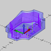
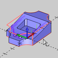
Now we create a Mill 3 Axis feature with two planar operations to rough and finish the material from the top of the model. We also explore modifying the CAD model before selecting geometry.
In this part we show you how to utilize the CAD Tree to modify existing geometry before selecting it for the feature. This is done so that the toolpath calculation ignores the holes and pocket which are already cut by other operations.
1 Click
the ![]() CAD Tree Manager
tab.
CAD Tree Manager
tab.
2 Right-click the first Extrude Cut feature, and click Suppress/Unsuppress.
The holes are temporarily removed from the model.
3 Right-click the second Extrude Cut feature, and click Suppress/Unsuppress.
The pocket is temporarily removed from the model.

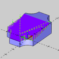
1 In the CAM Tree, right-click Machine Setup, and click Mill 3 Axis.
2 Click Select Geometry.
Drag a window to select the entire model.
3 Click
![]() to confirm the selection.
to confirm the selection.
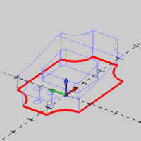
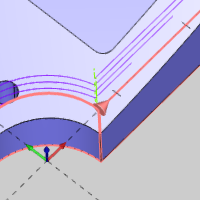
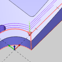
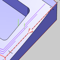
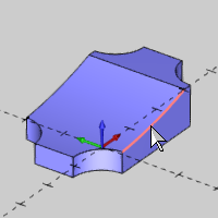
In this section we assign a boundary to limit the toolpath on the model. We use loop selection to easily select a 3D chain from the model.
1 Click Select Boundary.
2 Right-click the upper surface edge of the model, and click Loop Selection.
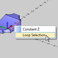
TIP: When using Loop Selection, the software automatically highlights two potential loops and you select the loop that you want to use as explained next.
3 Press S to turn off the shaded view and make it easier to view the two potential loops.
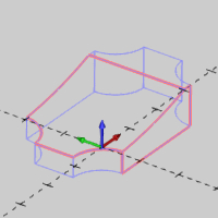
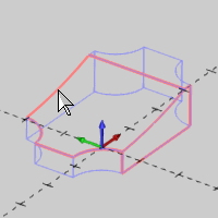
4 Click any edge of the upper loop that is not shared between the two loops.
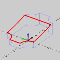
TIP: For this example, you could also select the top surface and allow the software to extract the edges to assign the boundary, which would provide the same result. When selecting a surface for a boundary, all edges (holes or pockets) are extracted. BobCAD-CAM provides multiple selection methods so you can quickly select geometry for all types of situations.
5 Press S to turn on the shaded view.
6 Click
![]() to confirm the selection.
to confirm the selection.
7 Click Next>>.
1 Under Material Approach, change the Rapid Plane value to 0.300.
2 Change the Feed Plane value to 0.200.
3 Click Next>>.
1 In the Machining Strategy under Standard, select the Planar operation template.
2 In
the Available Operations list,
click Planar, and click ![]() to add a second planar
operation to the Current Operations list.
to add a second planar
operation to the Current Operations list.
3 Click Next>> to update the tree with the new operations.
1 Click Next>>.
2 Click Tool Crib.
3 Under Tool Category, click Endmill Rough, and click Add From Tool Library.
4 Click the column name Diameter to sort the tool list.
Select the 0.500 inch diameter ball endmill with the 1.000 inch flute length (Tool Label: 1/2 Ball Rough Endmill - Standard).
Click OK.
5 Click OK in the Tool Crib.
1 Under
![]() Planar, click Parameters.
Planar, click Parameters.
2 Change the Stepover value to 0.125.
Change the Allowance XYZ to 0.015 to allow material for the finishing operation.
3 Under Bounds, select Step Down and change the value to 0.125.
We use all default values for the remaining parameters.
1 Under
![]() Planar 1, click Rough.
Planar 1, click Rough.
2 Click Tool Crib.
3 Select the 0.500 inch diameter ball endmill (Tool Label: 1/2 Ball Rough Endmill - Standard).
4 Click OK.
1 Under
![]() Planar 1, click Parameters.
Planar 1, click Parameters.
2 Change the Stepover value to 0.010.
1 Click Compute.
2 Hide the toolpath and collapse the feature.
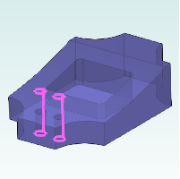
The final machining feature for this tutorial engraves text into the model. First we need to manage CAD layers to hide and show the appropriate geometry.
1 In
the ![]() Layers Manager,
right-click Solids, and click
Hide.
Layers Manager,
right-click Solids, and click
Hide.
2 Next
to Text, click ![]() to show the Text layer. (The icon changes to
to show the Text layer. (The icon changes to ![]() .)
.)
You can use the visibility button or the right-click menu to hide and show layers.
1 Right-click Machine Setup, and click Mill 2 Axis.
2 Click Select Geometry.
Click the text to select it, and click ![]() .
.
3 Click Next>>.
1 In the Total Depth box, change the value to 0.010.
Click Next>>.
1 Under Template, select the Engraving operation template.
2 Under
Engraving, click![]() Rough
to go to the tool page.
Rough
to go to the tool page.
1 Click Tool Crib.
2 Under Tool Category, click V-Tool, and click Add From Tool Library.
3 Select the 0.125 inch diameter V-tool with the 30.00 degree included angle (Tool Label: 0.125D-30DEG V-Tool).
Click OK.
4 Click OK in the Tool Crib.
1 Click Compute.

2 Hide the toolpath and collapse the feature.
Before simulating the program, we need to return the CAD model to its finished condition so that the workpiece displays properly in simulation.
1 In
the Layers Manager next to Solids, click ![]() to show the layer.
to show the layer.
Hide the Text layer.
2 In
the ![]() CAD Tree,
right-click the first Extrude Cut
feature, and click Suppress/Unsuppress.
CAD Tree,
right-click the first Extrude Cut
feature, and click Suppress/Unsuppress.
3 Repeat the previous step to unsuppress the second Extrude Cut feature.
You can also hide and show all toolpath in the job using the Machine Setup.
1 In the CAM Tree, right-click Machine Setup, and click Blank/Unblank Toolpath to sync the visibility of all features.
2 Repeat the previous step to show all toolpath.
3 Save the file.
Now we simulate the program to check for any necessary changes.
1 In the Modules menu, click Simulation.
2 In
the Simulation group on the Simulation tab, click the  Machine button so that it changes
to
Machine button so that it changes
to  Workpiece/Stock
focus.
Workpiece/Stock
focus.
3 In
the Visibility group, click the  Toolpath button to hide the toolpath.
4 Click
 to run the simulation, and adjust the
  speed slider
as needed.
speed slider
as needed.
5 Click
 to close the simulation.
Congratulations! You have completed the CAM portion of the Mill 3 Axis Standard demonstration file.
To learn more about simulation, view Getting Started with Simulation.